


We’d like to thank DG Matrix, Novos Power, and Aran Industries for their contributions and insights during the preparation of this deep dive.
Introduction: Welcome to the Power Chain Roller Coaster
Across every major industry conference in the first half of 2026, our research team kept walking past the same scene: a booth ten or fifteen people deep, leaning in to catch every word from another datacenter equipment messiah preaching the gospel of 800VDC. The pitch was the same every time. 800VDC is about to change the electrical infrastructure of the datacenter.
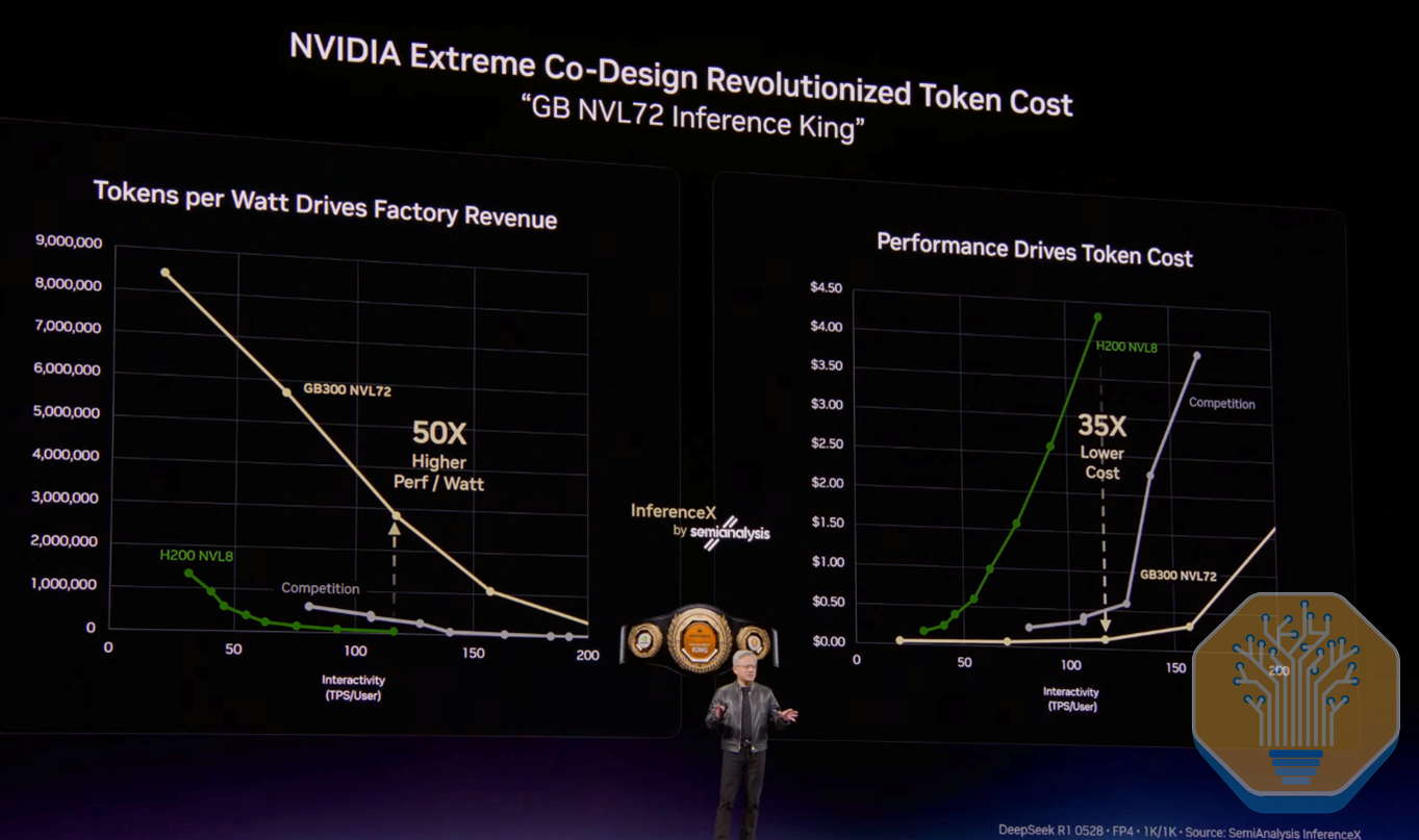
Every architectural shift looked excessive at first. Operators spent decades keeping water and leaks out of the data hall, then GPU thermal density made running coolant right up against the precious silicon unavoidable. Each shift happened anyway, because physics and the economics of compute do not negotiate. 800VDC is next, and the logic is the same. Tokens per watt are what matters.
Source: Nvidia, InferenceX
As GPU clusters become increasingly dense, with Kyber Ultra approaching 660kW per rack, the physics start to break down. Resistive losses scale with current squared, and at these power levels copper mass and thermal envelope exceed what fits inside a rack. Moving to 800VDC eliminates conversion stages, reduces resistive losses, and cuts facility-level power consumption by ~5%. At 1GW of IT load, that is over 50MW of continuous savings, tens of millions in annual electricity costs, or new compute capacity unlocked. For all the inference-king proponents out there, 800VDC is a transition forced by physics and motivated by system economics.
We have been tracking this transition through our InferenceX and Industrials Models, which provide a bottom-up view of where efficiency gains materialize and which equipment categories absorb the disruption. The Industrials Model includes a dedicated 800VDC module, building up from individual accelerator architectures to a top-down view of 800VDC penetration, MW adoption, and market sizing for equipment like the power sidecar and Solid-State Transformers (SSTs).
Source: SemiAnalysis Industrials Model
This deep dive traces the transition phase by phase: from the sidecar retrofit, through faciliy-level DC distribution, to the SST endgame. For each phase, we analyze the BoM and map the changes in equipment content/MW, what survives, what gets redesigned, and what gets eliminated.
The 800VDC revolution is set to dramatically change the revenue trajectory of certain suppliers. We’ve been tracking winners and losers for over a year in Industrials Model, which estimates the BoM for 20+ different datacenter designs broken down into 70+ equipment types and lays out the impact for 500+ suppliers. It is built on our industry-leading Datacenter Model which forecasts quarter-by-quarter MWs for 6000+ datacenters and anticipates design changes.
This has enabled us to successfully call out both winners, and companies inaccurately pictured as losers by the market, before anyone else. If you are wondering whether UPS systems have a place in upcoming 800VDC distribution, what is the market opportunity for SSTs, or which suppliers are leading this transition, stick with us.
Source: SemiAnalysis Industrials Model
Part 1 of this 800VDC Revolution series covers datacenter layout and equipment implications. Part 2 will focus on power electronics and the semiconductor revolution underneath it.
Understanding The Basics: What is 800VDC and Why It’s Inevitable
At its simplest, 800VDC in this context means distributing power at ~800 volts direct current through the data hall or row and into the rack, then stepping it down near the compute. The number 800 is not arbitrary, but a voltage high enough to materially reduce current (and therefore copper loss and thermal burden) while remaining within the broad regulatory and product-safety classification of “low-voltage DC” in many jurisdictions. For context, EU rules around the Low Voltage Directive scope reference DC equipment ratings up to 1,500 V DC (and AC up to 1,000 V).
Current datacenter electrical architectures generally rely on AC distribution at the facility level. Datacenters today use three-phase AC at 415V or 480V, and the topology relies on conventional UPS architectures before distributing 48-54V DC within the rack.
This works at today’s rack power levels, but starts to fail as rack densities in the next two years approach ~600 kW+, for several reasons:
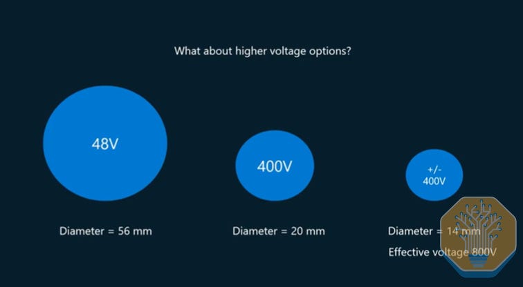
Copper becomes unmanageable at 48–54 V. A 1 MW rack at 48–54 VDC needs ~200 kg of copper busbars. At 1 GW scale, that’s hundreds of tons of copper — brutal on cost, weight, installation complexity, and routing space.
Source: Microsoft
Power shelves crowd out compute. Today’s NVL72 racks already use up to 8 power shelves. At Kyber-class rack power, a 48–54V approach would require ~64U-equivalent of power hardware, effectiviely an entire rack, leaving no volume for compute.
Current becomes the real limiter. Delivering 600 kW at 48–54 V implies ~12,500A. At 800 V, that drops to ~750 A (~16.7× less), enabling dramatically smaller conductors/busbars and far lower thermal stress. If conductor resistance were held constant, I²R losses fall ~278×, so in practice you shrink copper and “buy” size/weight reductions.
Conversion losses compound and hurt reliability. Stacked AC-to-DC and DC-to-DC stages reduce end-to-end efficiency, increase heat, and introduce failure points, raising cooling loads, downtime risk, and maintenance costs.
At the end of the day, 800VDC is the physics enabler for 2,300W TDP chips and 600kW racks, and those 600kW racks are the direct consequence of the push for density, because density is what drives cost per token down. Cost per token is dictated by the size of the scale-up world you can build at full NVLink bandwidth: bigger domains mean wider Expert Parallelism (EP) / Tensor Parallelism (TP), MoE routing on NVLink rather than scale-out, and less serialization across decode. As we laid out in our Vera Rubin Deep Dive and GTC 2026 pieces, Nvidia’s design rule is to pack compute tightly enough that copper reaches everything in the rack. Reiner Pope made this point cleanly on our friend Dwarkesh’s podcast a few weeks ago, indicating that a single rack bounds the size of the expert layer you can build, because the moment an all-to-all crosses a rack boundary, it falls onto a scale-out fabric that is roughly eight times slower than NVLink.
Bigger scale-up worlds mean denser racks, denser racks mean 600kW envelopes, and 800VDC is what makes those envelopes possible.

Source: SemiAnalysis AI Networking Model
The Four Chapters of the HVDC Transition
The move to 800VDC is a complex metamorphosis that rewrites the entire electrical architecture, introduces new safety standards, requires new regulatory frameworks, and, most importantly, forces operators to make very different strategic choices about when to walk away from their legacy AC distribution.
Source: SemiAnalysis
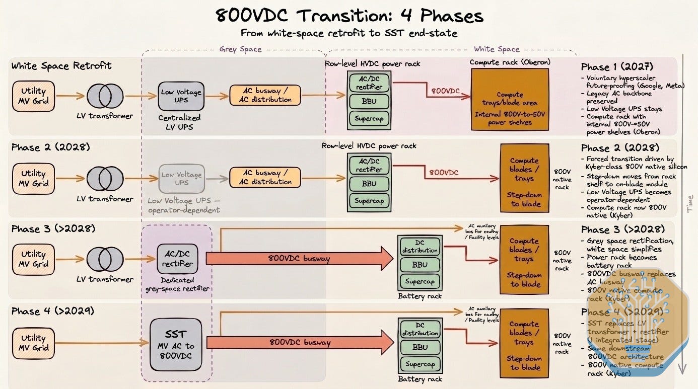
We frame the 800VDC transition as progressing through four distinct phases. Phases 1 and 2, starting in late 2026 / early 2027, retrofit the existing AC distribution into 800VDC at the rack level via the power rack. Phase 1 is the early-mover stage, driven by hyperscalers willing to pay up for future-proofing and efficiency gains. Phase 2 kicks in once 800VDC-native systems begin shipping at volume. Phase 3 rewrites the electrical architecture itself, taking 800VDC distribution facility-wide. Phase 4 is the end state, built around new pieces of equipment that promise to render much of today’s electrical stack obsolete.
Source: SemiAnalysis Industrials Model
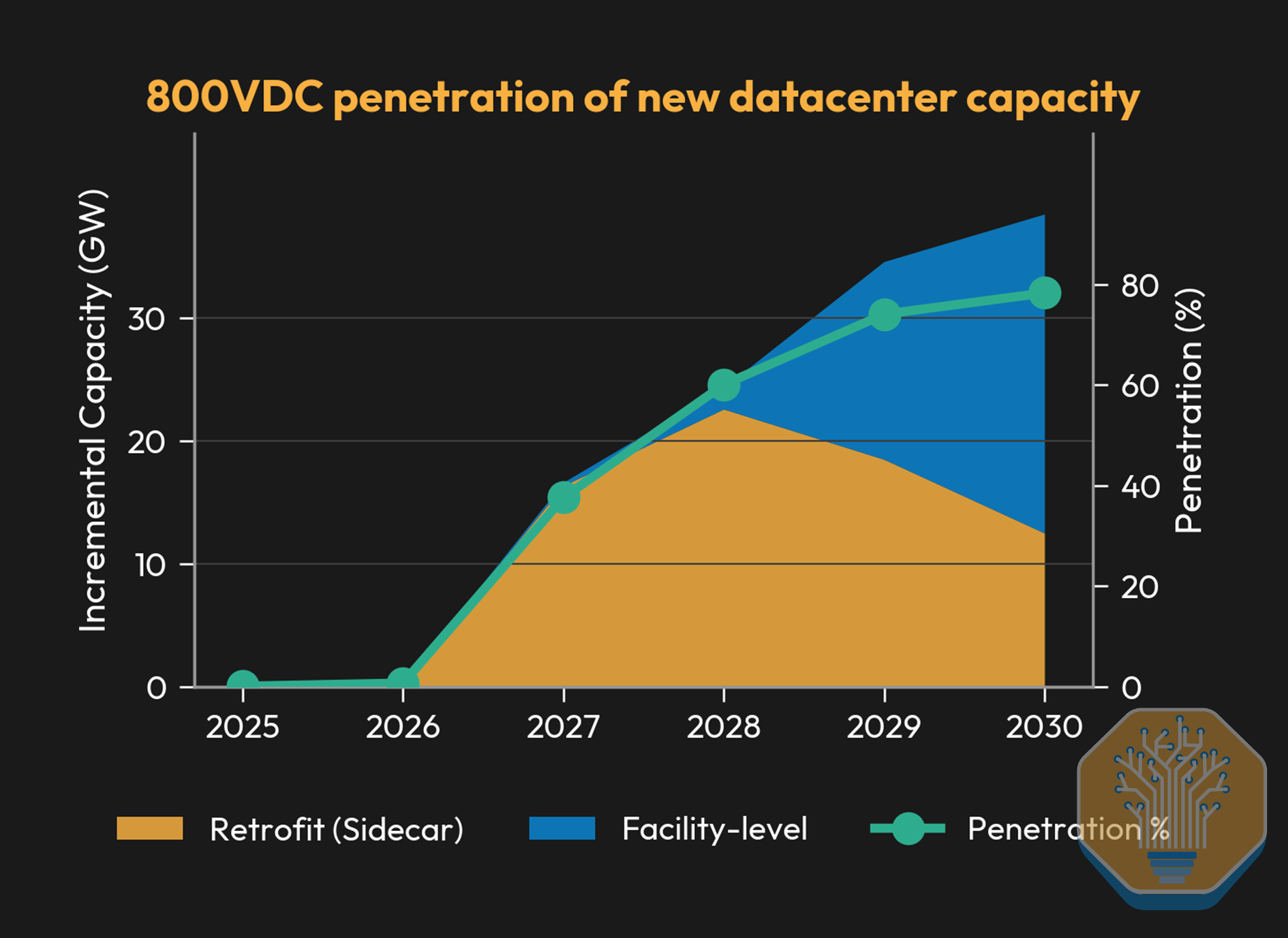
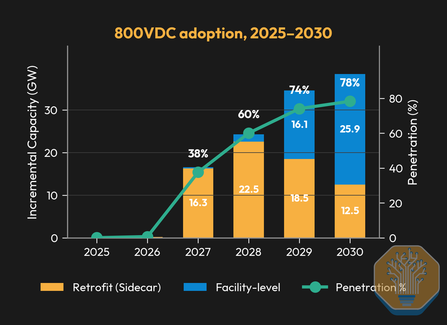
The result is a progressive adoption curve for 800VDC. We expect total incremental capacity powered by 800VDC to reach ~39GW by 2030. Through Phases 1 and 2, all addressable capacity is served by sidecars, since the underlying facility is still AC-distributed and the conversion happens at the power rack. The mix inflects in 2029 as facility-level HVDC distribution becomes viable and the first 800VDC-native sites come online, shifting the conversion stage upstream from the rack to the SST or MV rectifier.
Source: SemiAnalysis Industrials Model
Before diving into how the datacenter layout changes, we encourage readers to revisit Part 1 of our datacenter anatomy series, which explains many of the core concepts behind datacenter electrical equipment.
Phase 1 (2026/2027): The White Space Retrofit
Source: SemiAnalysis Industrials Model
The HVDC journey begins primarily with two operators, Google and Meta. Both have been pushing their 800VDC architectures through the OCP working groups for over 18 months, most visibly with the Mt. Diablo reference design, first announced in October 2024 and published as an open specification in May 2025. Neither is being forced into the transition, but they are doing it to take a leading position in the upcoming shift and because they want to squeeze every megawatt and every point of efficiency out of their existing power chain before the rest of the market is forced to catch up.
This matters because 800VDC is not yet a hard requirement. The chip generations ramping in late 2026 and 2027, like Vera Rubin NVL72, top out at rack densities of 180-220kW. Three-phase AC can still deliver that without hitting the physical limits of conductor sizing or distribution losses. Phase 1 is therefore voluntary future-proofing, not a forced response to a hardware constraint.
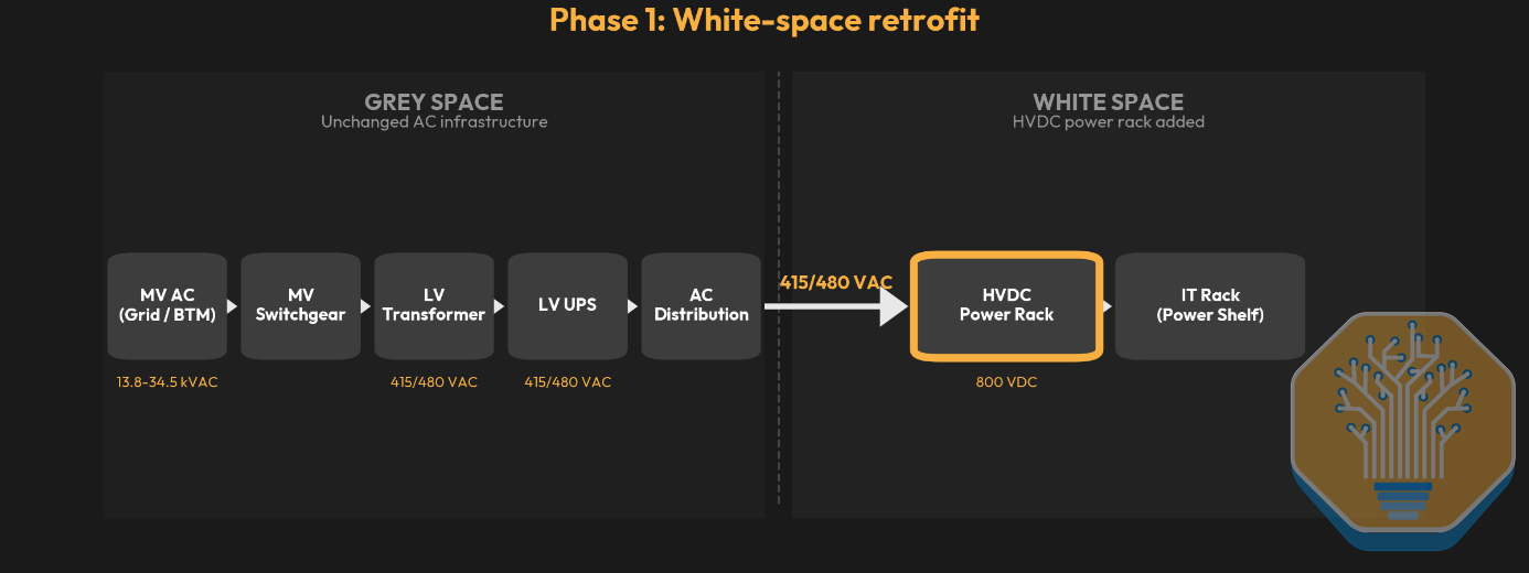
This initial phase kicks off the “White Space Retrofit” era. New HVDC hardware, primarily a row-level cabinet called the HVDC power rack, layers on top of existing white space infrastructure rather than replacing it. The datacenter’s electrical backbone stays intact. Same transformers, same UPS, same switchgear, same ATS.
Power Flow Overview with HVDC Power Rack
At the facility level, Medium-voltage AC enters the grey space and is stepped down via transformer to 415V or 480V three-phase AC. That feeds into a UPS, which performs double conversion (AC-DC-AC), then outputs 415V AC. AC is then distributed through the data hall via busway. So far, this is the traditional power flow we have extensively covered in previous articles.
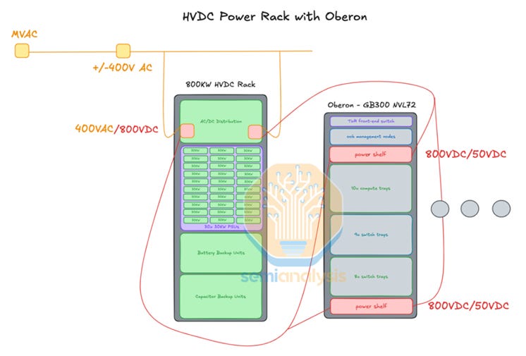
The change occurs when we get closer to the IT racks. Instead of feeding 415V directly into in-rack power supply units, the AC feed now terminates at a standalone 42U cabinet named the HVDC power rack deployed at the row level.
Source: SemiAnalysis
The rack receives AC from the overhead busway and outputs 800VDC through cable to adjacent IT racks. Inside, it performs three jobs: rectification of 415V AC to 800VDC, BBU modules for ride-through during outages, and optionally, capacitor shelves for transient buffering during GPU load spikes.
In a Nutshell: The Power Rack
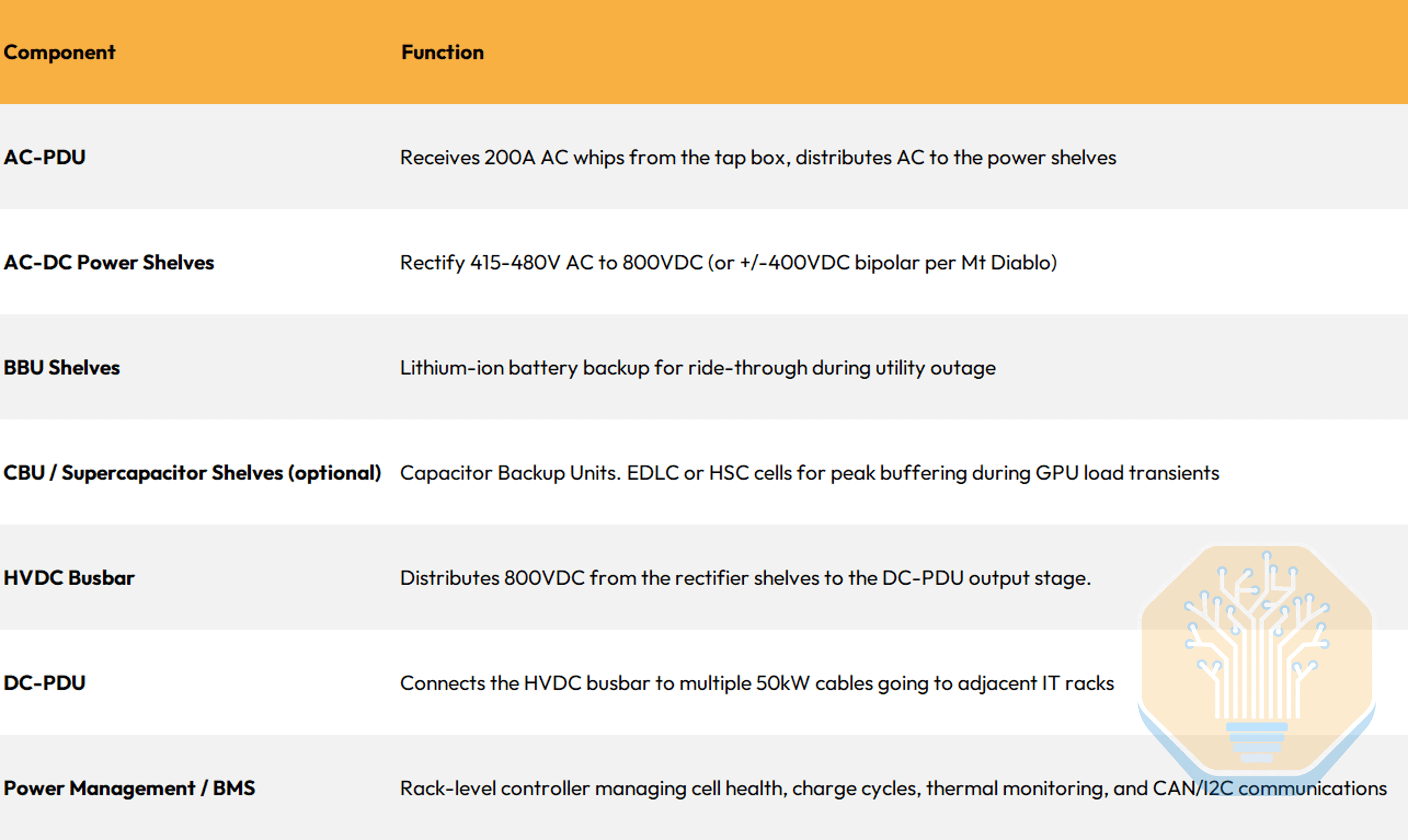
It is worth looking in more detail into the building block that underpins Phases 1 and 2 of the 800VDC transition: the disaggregated power rack. This is a dedicated rack that consolidates AC-to-DC rectification, energy storage (BBU and/or capacitor bank), and power management into a single unit, freeing the compute rack to be entirely dedicated to GPUs, networking, and cooling. Microsoft’s Mt Diablo project originated the concept; the OCP Diablo 400 specification, co-authored by Google, Meta, and Microsoft, standardizes it.
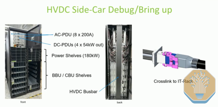
Key components that are commonly found in a sidecar power rack:
Source: Rittal
Source: SemiAnalysis
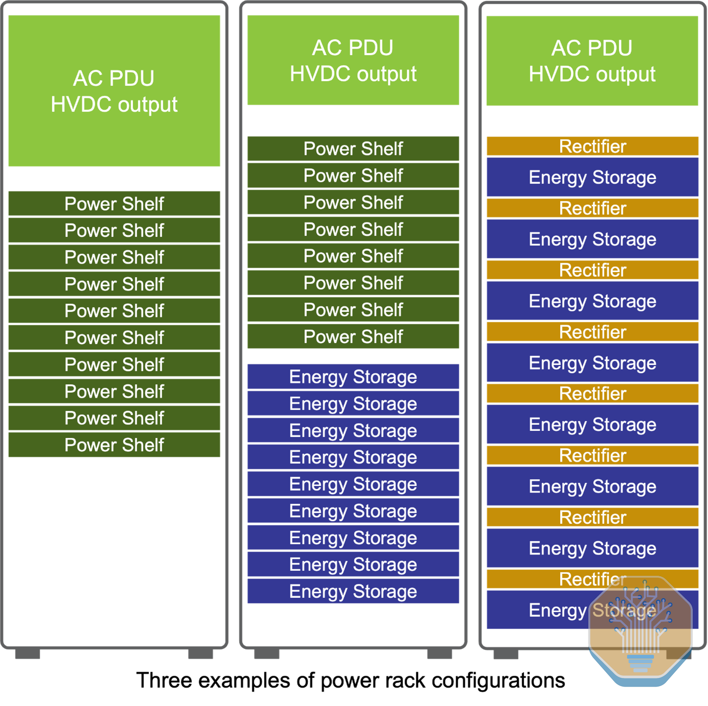
But the sidecar concept did not emerge fully formed. It evolved through several OCP rack and power specification versions. The earlier iterations (ORv2 at 12V, ORv3 at 48V, and the HPR V1/V2 variants that pushed single-rack 48V designs up to ~190 kW with liquid-cooled busbars and upgraded 72 kW power shelves) are covered in our Datacenter Anatomy series. Here we focus on the versions directly relevant to 800VDC: the disaggregated sidecar designs where the voltage transition occurs.
Source: OCP
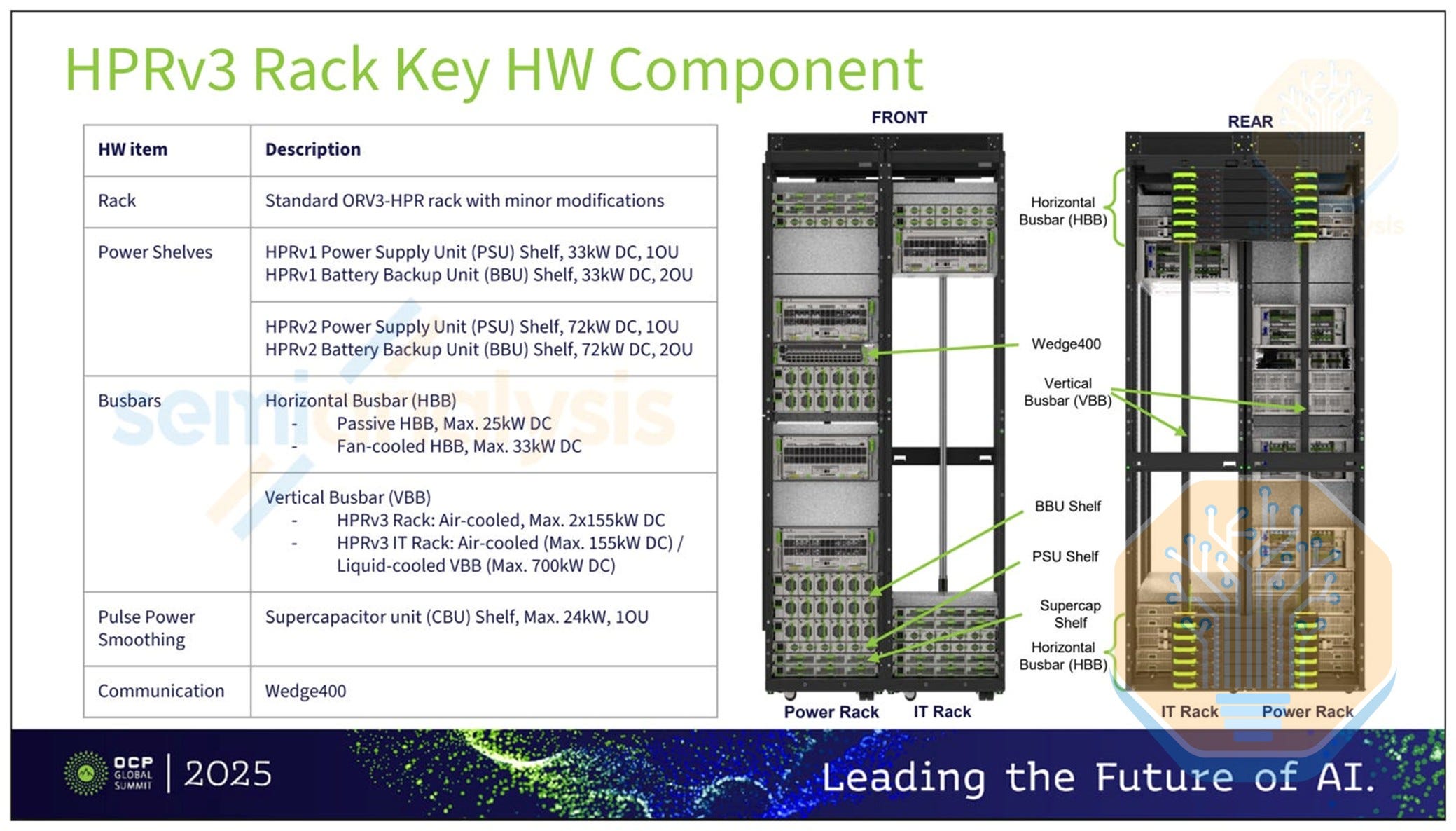
ORv3 HPR V3: The Disaggregation Threshold (50V Sidecar, up to 300 kW)
HPR V3 is really where power and compute separate into distinct racks, the genesis of the “sidecar” concept. PSU and BBU shelves move into a dedicated 50VDC side power rack connected to the IT rack through horizontal busbars at the top and bottom of both. Both remain ORv3 HPR standard form factor. Power capacity tops out at 300 kW, limited by the horizontal crosslinks and the air-cooled vertical busbar inside the power rack.
Source: OCP
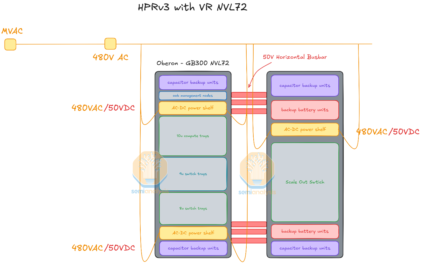
The insight is putting power conversion hardware in a rack optimized for power, with appropriate cooling, safety, and serviceability, rather than cramming it into a rack optimized for compute. The V3 power rack can be serviced independently, shrinking the blast radius of power-side failures. But V3 still distributes at 50VDC, which means busbar currents remain high (6,000A at 300 kW) and the crosslinks become the bottleneck.
Source: SemiAnalysis
This persists today. Even the VR NVL72 rack, when fed by an HVDC power rack at 800VDC (Nvidia spec) or ±400VDC (OCP spec), still distributes internally over a 50V busbar. A DC-DC power shelf inside the rack steps the high-voltage DC down to 50VDC before it reaches the compute trays. At the far end, VRMs on the GPU board convert from 50V to sub-1V.
We have more detailed power and architecture details in our VR NVL72 Component BoM and Power Budget Model.
ORv3 HPR V4: HVDC Sidecar at +/-400VDC (up to 800 kW)
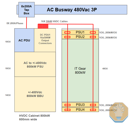
HPR V4 is the version that bridges the OCP HPR lineage into the HVDC era. It makes two critical changes: the voltage steps up from 50VDC to +/-400VDC (800V total), and the busbar-based crosslink is replaced with discrete power cables.
Architecture: PSU and BBU shelves move into a +/-400VDC side power rack, which also houses AC input and DC output PDUs
Power delivery: The power rack connects to the IT rack through 16x 50 kW HVDC cables (replacing the horizontal busbars of V3), each carrying +/-400VDC
Power capacity: Up to 800 kW maximum. If capacitor-based energy storage (CBUs) occupies half the BBU slots, effective capacity drops to ~400 kW
AC input: 200A single conductor wire from tap boxes
Form factor: Same ORv3 HPR rack dimensions as V3
Why cables instead of busbars: At the power levels V4 targets (400-800 kW), the horizontal busbar crosslinks from V3 become current-limited. Replacing them with discrete cables allows each cable to be independently routed, fused, and managed, and eliminates the single-point busbar as a thermal and mechanical constraint
V4 effectively represents the “pre-Diablo” state of HVDC sidecar design, developed primarily by Meta’s rack and power team. It proved the concept of disaggregated HVDC power delivery but was not yet a multi-vendor, multi-hyperscaler specification.
Source: Meta
The Diablo 400 Specification: Standardizing the HVDC Sidecar
The Diablo 400 specification (named after Mt Diablo, Microsoft’s original internal project name) formalizes and standardizes the HVDC sidecar concept that HPR V4 pioneered. Co-authored by Google, Meta, and Microsoft, Diablo 400 was released as a draft specification (v0.5.2) in May 2025, with a subsequent v0.7.0 revision following industry feedback.
What Diablo 400 standardizes that HPR V4 did not:
Multi-vendor interoperability: Standardized electrical and mechanical interfaces so that PSU shelves from Delta, power management from Advanced Energy, busbars from TE Connectivity, and BBUs from multiple suppliers can all work together in a single rack
Dual voltage support: The base specification defines +/-400VDC bipolar as the standard configuration (3-wire: +400V, -400V, and Common/Midpoint/Return at the rectifier shelf output), with 800VDC monopolar as an explicit design option (2-wire: 800VDC and Return, safety-isolated from PE ground)
Power range: 100 kW to 1 MW per IT rack
PSU design: 3-phase AC input, +/-400VDC output. PSU modules are front-of-rack accessible, hot-swappable, and hot-pluggable, with droop and active current sharing between PSUs and power shelves
Cable spec: Voltage drop budget of 0.1% at 5m cable length for output cables between power rack and IT rack
Holdup time: Minimum 20 ms without energy storage at 100% loading; distributed holdup acceptable between the AC/DC PSU in the Diablo 400 rack and downstream DC/DC converters located outside the rack
Mechanical: Sliding shelves for push-in/pull-out of large building blocks (e.g., 4OU BBU), blind-mate connectors with static rail/sliding rails for PSU/BBU/CBU hot-swap
Seven standardization areas: Connectivity, power rack form factor, AC-DC PSU topology, DC-DC modules, redundancy architecture (single/dual feed, N+x), safety standards for HVDC and liquid-cooled systems, and data/power management backplane
The choice of 400VDC as the nominal voltage was deliberate. As Google’s engineers stated at OCP EMEA 2025: “selecting 400 VDC as the nominal voltage allows us to leverage the supply chain established by electric vehicles, for greater economies of scale, more efficient manufacturing, and improved quality and scale.” In the bipolar configuration, each individual rail sits only 400V from the grounded midpoint, keeping the system within the voltage range where mature EV-grade power electronics (650V GaN FETs, 400V-class capacitors, connectors, and fuses) can be used directly.
No One-Size-Fits-All
There is no one-size-fits-all 800VDC power rack. Yes, Diablo 400 provides a shared base specs, but the reality on the ground is fragmented. Nvidia sits entirely outside it and is developing a monopolar 800V reference design at 660kW, with air-cooled samples and production in mid-2026, and a liquid-cooled VR Ultra variant sampling in late-2026.
Even within Diablo 400, the three co-authors diverge meaningfully. Meta runs 600-800kW with 50kW HVDC output cables and 8x 200A AC input whips. Google push to 900Kw by reallocating rack space from BBU and supercap slots to PSUs, run 100kW output cables, and need 12 AC whips at the 1.1MW roofline. Amazon’s design lands at 800kW on ±400V. Microsoft co-authored the spec but we believe they are making slower progress.
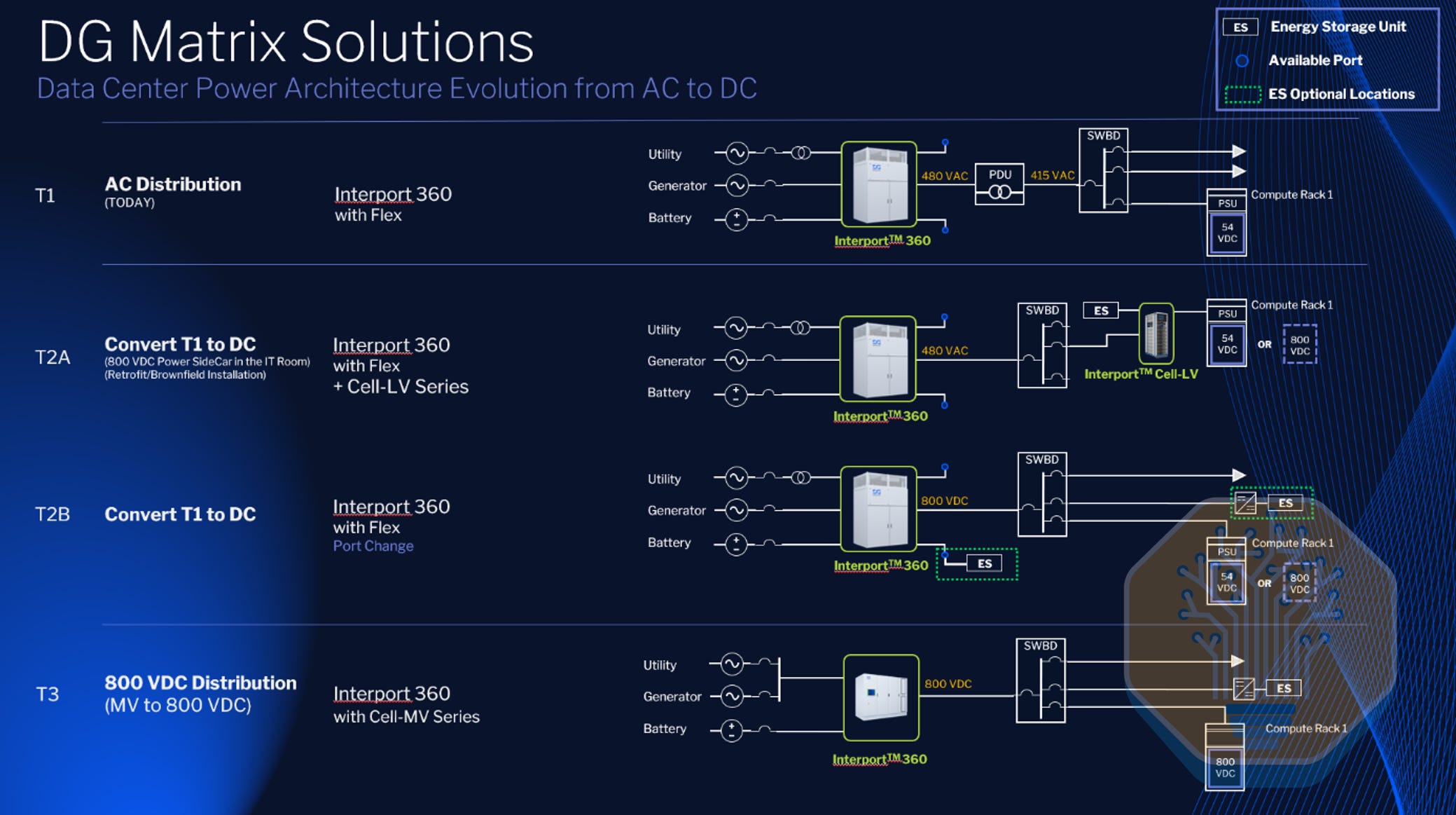
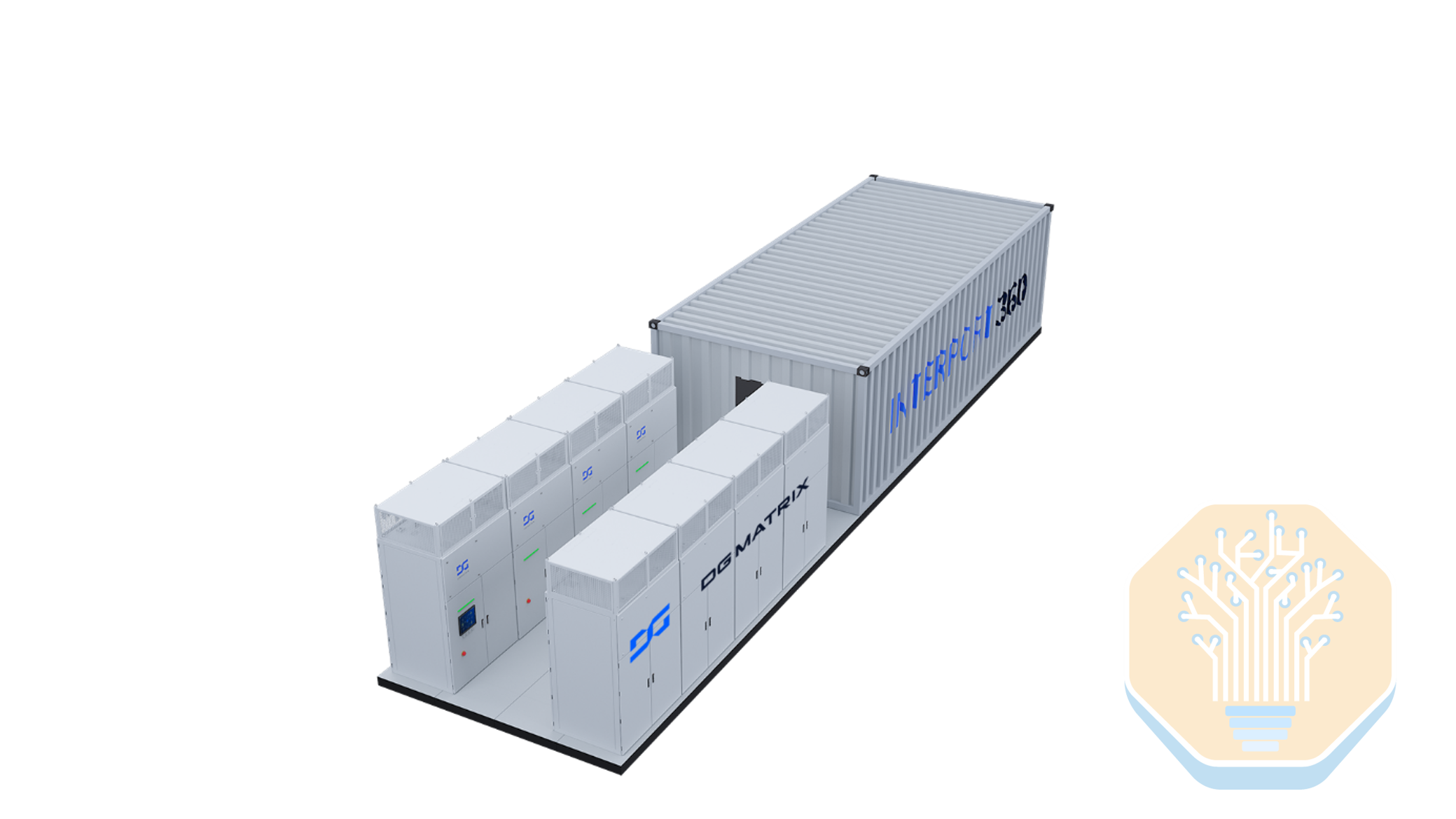
Besides, an alternative sidecar topology uses an LV-input SST in place of the conventional rectifier-plus-PSU stack, like DG Matrix’s Interport Cell Series.
Source: DG Matrix
The cost of the power rack
The HVDC power rack is the headline new-equipment cost in the early retrofit phases. We estimate the ASP for the Power Rack to reach $400-500k per unit, roughly 10x the ~$40k ASP of standard AC power-rack equipment. On a deployed-MW basis, that lands near $500k/MW.
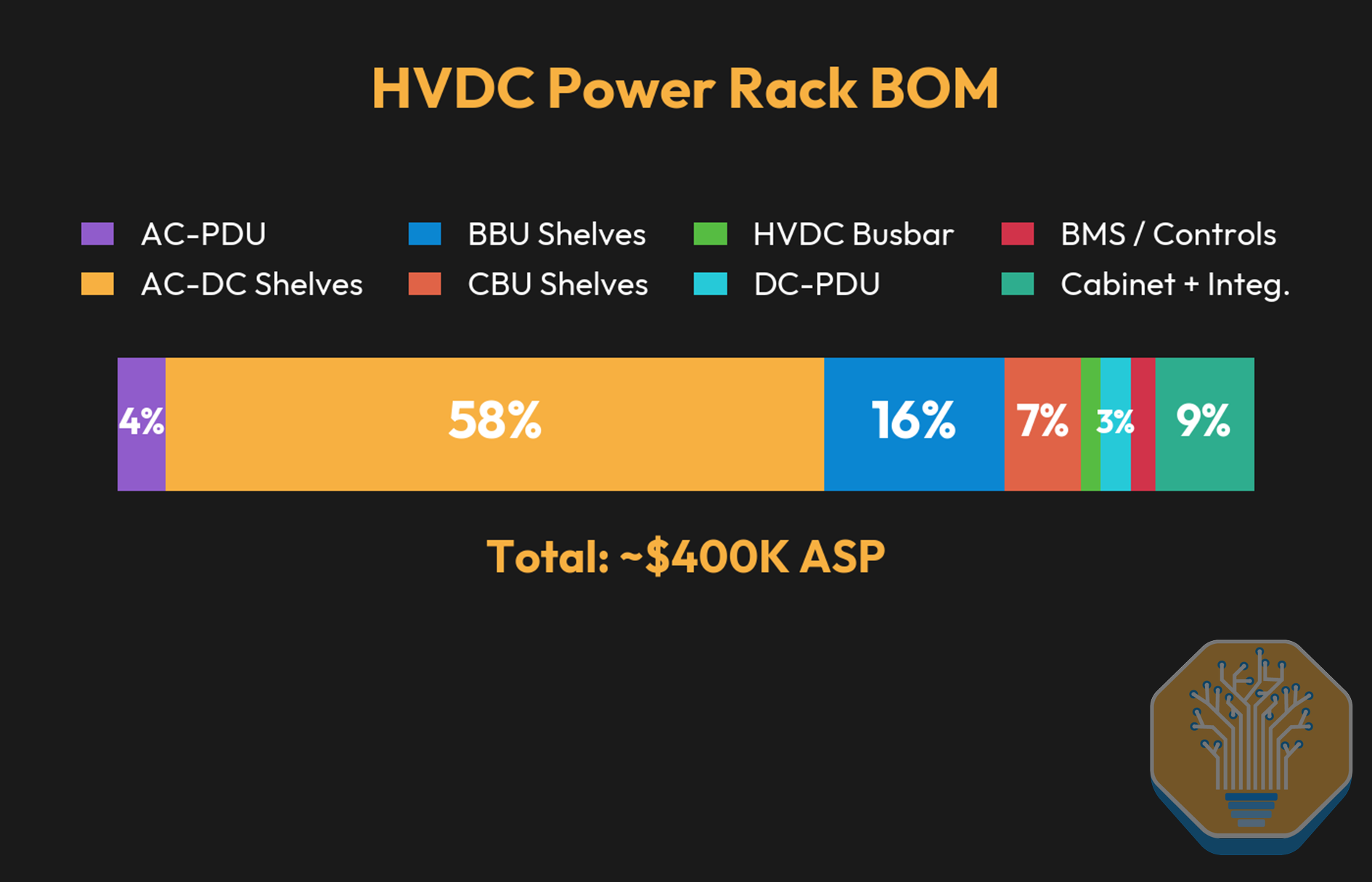
Source: SemiAnalysis Industrials Model
The Sidecar Market Opportunity and TAM sizing
In our SemiAnalysis Industrials Model, we size the 800VDC equipment TAM, specifically for the sidecar (power rack) and Solid State Transformer (SST), by applying this phase-by-phase adoption timelines to incremental datacenter capacity build and doing a chip-by-chip SKU calculation.
We expect sidecar TAM to peak at ~$11B in 2028 before declining as facility-level 800VDC takes share in Phase 3. We assume a power rack content of $0.5M/MW.
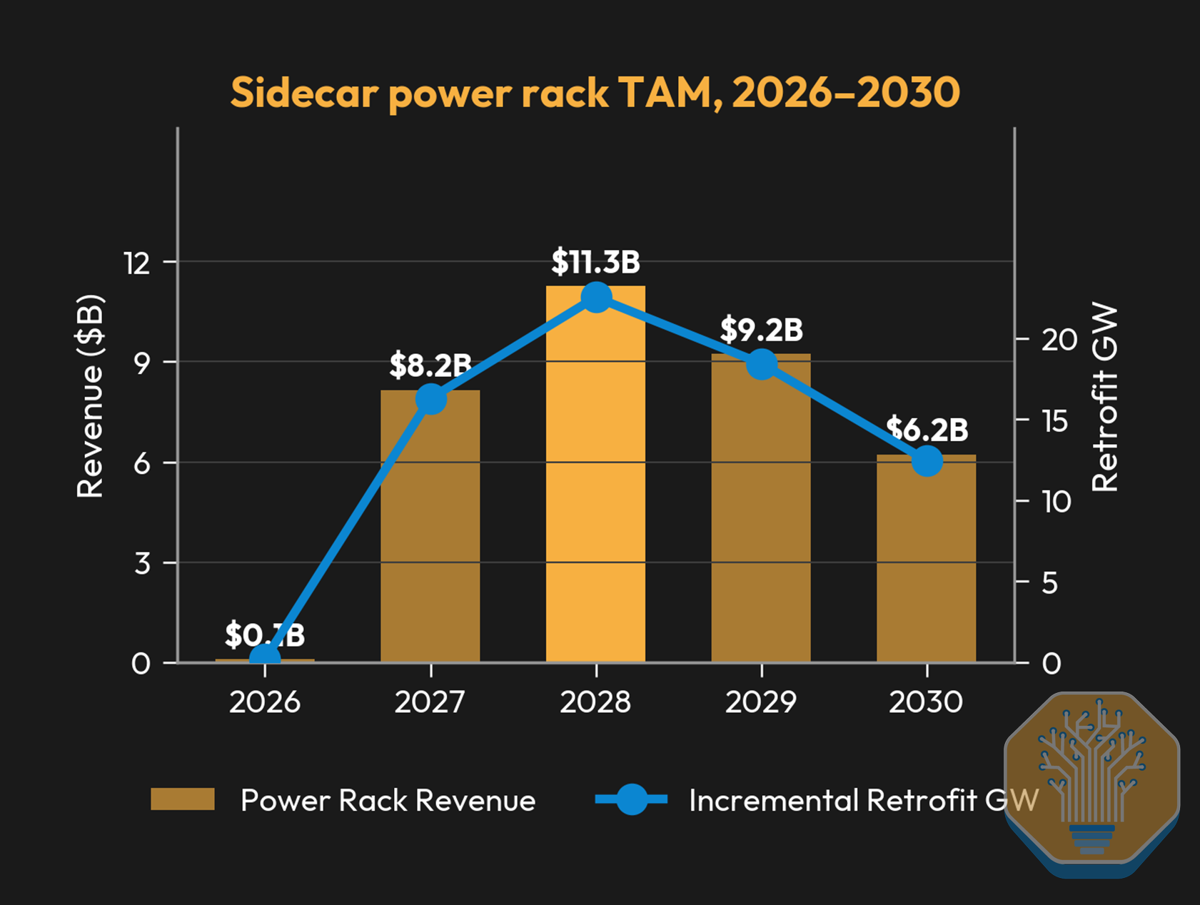
Source: SemiAnalysis Industrials Model
Phase 1 Summary
The white-space retrofit represents a clear cost uplift in electrical content/MW versus current architectures, because Phase 1 essentially deletes nothing. We estimate the delta at roughly +$400-500k/MW, with the HVDC power rack accounting for the large majority.
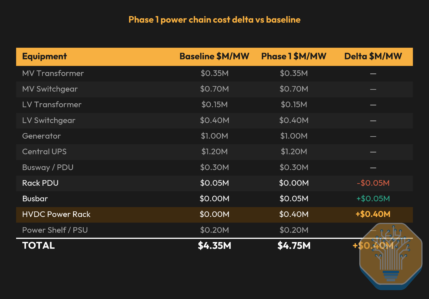
Source: SemiAnalysis Industrials Model
Phase 2 (2027/2028): The Turning Point Comes with 800VDC-Native Compute
Source: SemiAnalysis Industrials Model
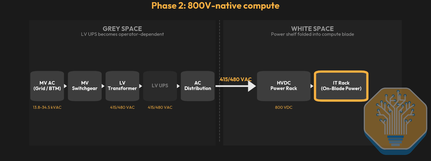
Phase 1 was the start of the retrofit era. The real inflection point comes with the arrival of 800VDC-native systems. At that point, 800VDC stops being a future-proofing pilot and becomes a mandatory transition forced by physics and rack density. Operators electrifying the Kyber Rack have no AC fallback at the rack inlet, and we expect 800VDC penetration to spike sharply in this window. Because 800VDC-native silicon will land before facility-level 800VDC distribution is ready, the retrofit phase persists.
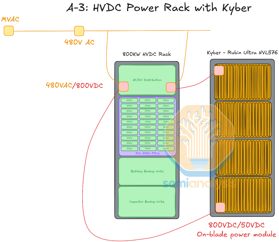
Source: SemiAnalysis
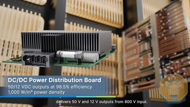
Architecturally, Phase 2 looks very similar to Phase 1. Both retrofit the white space with the HVDC power rack, both leave the grey space intact, and both rectify AC to DC in the row-level power rack. The key difference is where the voltage steps down to chip-usable levels. In Phase 1 (Oberon rack), a power shelf inside the IT rack converts 800VDC to ~50VDC before it reaches the compute trays. In Phase 2 (Kyber rack), the 800VDC bus runs directly to the compute blade, and an on-blade power module handles the final step-down to 50V.
Earlier Kyber designs shown at OCP depicted a DC-DC PSU sidecar adjacent to the compute rack, but we now believe this approach is unlikely to be adopted at scale. A standalone sidecar consumes more aggregate floor and rack space than integrating the conversion stage into the blade itself, and the power module form factor has proven feasible within the compute tray’s volume constraints.
Source: Delta
Because most servers and trays still take roughly ~50V input, both architectures retain a high-power 800V-to-~50V DC-DC conversion stage. The difference is where that conversion happens.
Some discussions have explored delivering 800VDC directly into the compute tray and stepping it down to an intermediate bus voltage (IBV) before further conversion to point-of-load rails. While Kyber’s on-blade power module does accept 800V input, it converts to the established ~50V bus level rather than an IBV scheme. A full 800V-to-IBV-to-PoL architecture within the tray remains extremely challenging given the limited space and safety constraints involved.
What Happens With UPS and Battery Storage
Traditional central UPS systems are probably the most contested piece of infrastructure in the 800VDC transition. In the 800VDC architecture, we expect centralized Low Voltage UPS systems to progressively lose their role and eventually become obsolete. In the retrofit era, the power rack sits directly on the 800VDC bus and houses BBU modules and supercapacitors, which we cover shortly. Both are natively DC-coupled. BBUs bridge seconds-to-minutes during outages and supercapacitors absorb millisecond-scale GPU load transients. Together, they replace the centralized short-term battery storage and UPS ride-through function without the 2-3% conversion loss of an AC-DC-AC UPS pair.
As we covered in our electricals deep dive note, Google and Meta already took this aggressive approach years ago, bypassing the central monolithic UPS with “distributed UPS” architectures. In their architecture, AC power is distributed directly to the rack, the in-rack PSU handles AC-DC conversion, and rack-level Li-Ion Battery Backup Units (BBUs) provide the short-duration bridge power. This removes the central UPS’s AC-DC-AC conversion pair and improves efficiency, while also cutting in half the total battery capacity needed for the datacenter, since there is no longer a need for both an A-side and a B-side UPS.
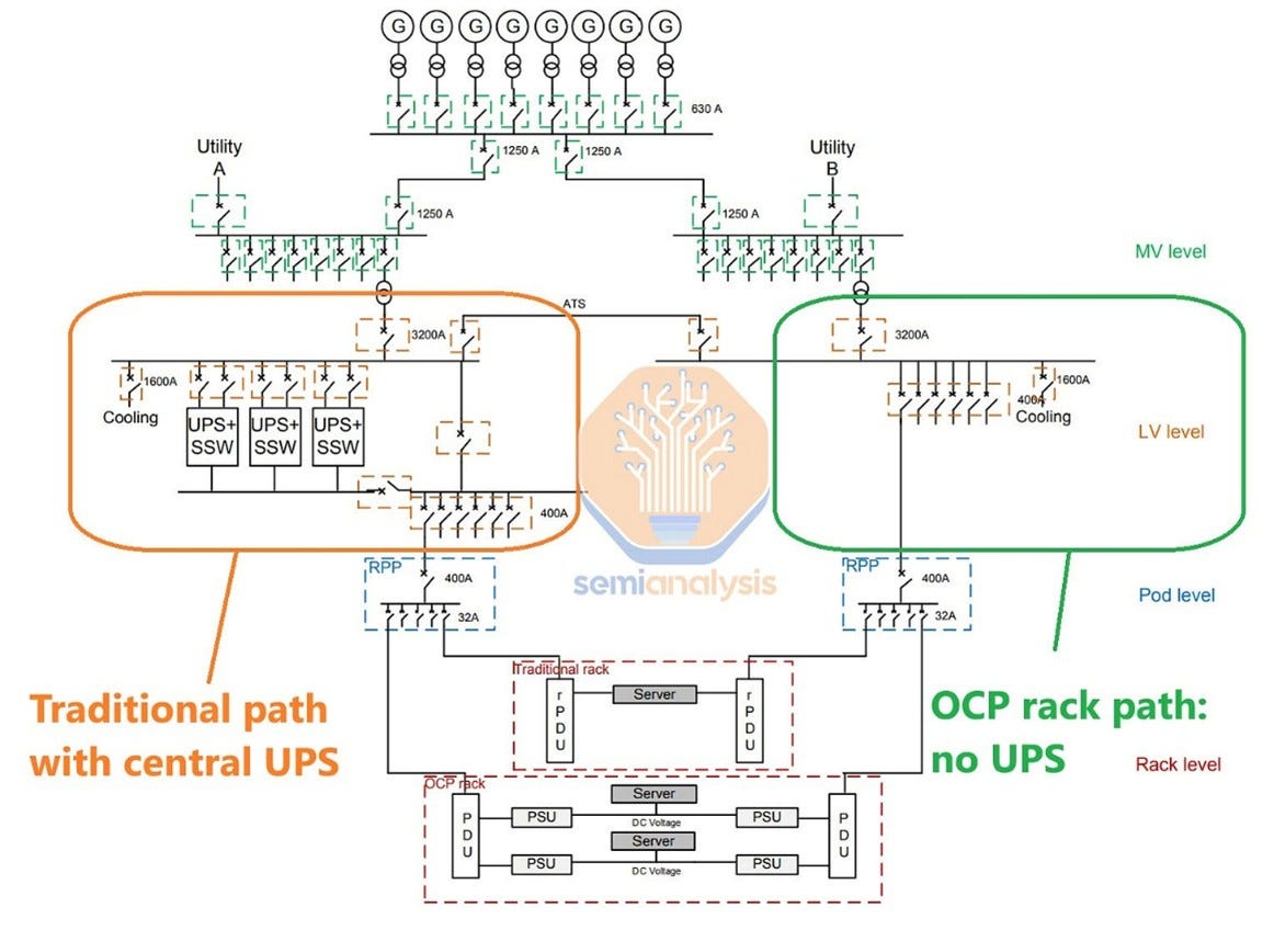
Source: SemiAnalysis
That said, managing distributed UPS or battery backup is more operationally challenging than running a traditional central UPS. We expect operators other than vertically integrated hyperscalers like Google and Meta to keep the Low Voltage UPS in place for redundancy and load fluctuation management, at least in the medium term.
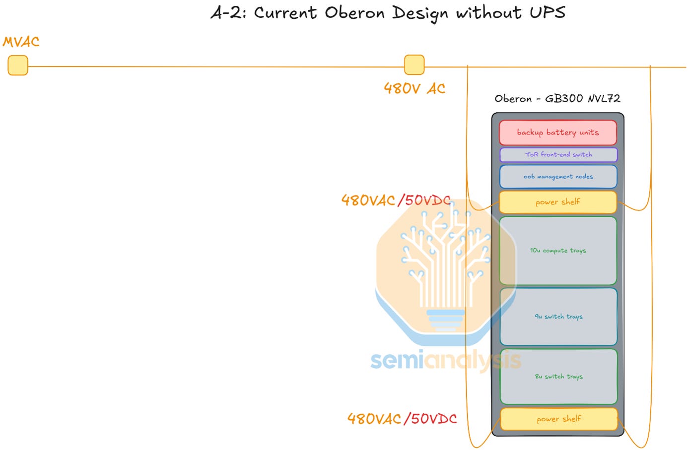
Source: SemiAnalysis
This is especially true for colocation providers, which prioritize flexibility and need to support mixed workloads: CPU racks, storage arrays, networking equipment, and older GPU racks that still run on AC. Keeping the grey-space AC infrastructure intact lets these operators deploy 800VDC for their densest AI racks while running standard AC distribution for everything else.
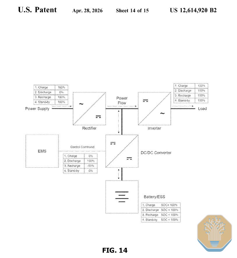
We expect different operators to adopt different architectural approaches to backup, and new alternatives are emerging. Medium Voltage UPS, operating at 4.16-34.5 kV directly at the grid connection point, is functionally similar to the rack-level Battery Rack but centralized at the grid interface rather than distributed across the data hall. ABB’s HiPerGuard runs at 98% efficiency and is already deployed at Applied Digital’s 400MW North Dakota AI campus. ON.energy was awarded few weeks ago a US patent that protects their MV double-conversion UPS architecture. The second alternative is facility-level BESS, which as we covered in our deep dive operates at megawatt-to-hundreds-of-megawatts scale, provides 1-4 hour duration backup, and increasingly replaces or shrinks the diesel generator.
Source: United States Patent and Trademark Office
Phase 3 (late 2028/2029): Redesigning the Electrical Architecture With a Centralized Rectifier
Source: SemiAnalysis Industrials Model
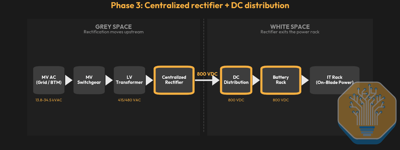
In Phases 1 and 2, the AC-DC conversion happens close to the rack, inside the row-level HVDC power rack. Phase 3 changes the datacenter layout itself, and 800VDC becomes the building’s electrical core. This is the true inflection point, where things start to become interesting. Let’s unpack what happens in each area of the datacenter.
What Happens in the Grey Space: Power Distribution Goes DC
In Phase 3 a dedicated upstream rectifier that sits in the grey space or outdoors converts 415V AC to 800VDC, distributing DC across the entire hall. These are mature units using silicon IGBTs or thyristors rated at 1200-1700V.
The grey space splits in two. MV transformers connecting the datacenter to the grid are unchanged. MV switchgear stays because the utility feed is still AC, and the upstream MV infrastructure (11-34 kV) is expected to grow more complex as facilities scale to gigawatt clusters. LV transformers remain, stepping MV down to 415V AC for the upstream rectifier. The 480V AC switchgear between LV transformers and PDUs has no role once 800VDC flows through the busway, and AC floor PDUs are eliminated along with it, since the DC busway feeds the battery rack directly with no AC distribution PDU in between. In summary, everything above the AC-DC conversion point stays, while everything below it, designed for AC distribution, goes.
Understanding DC Distribution: Switchboards, Busway, and Protection
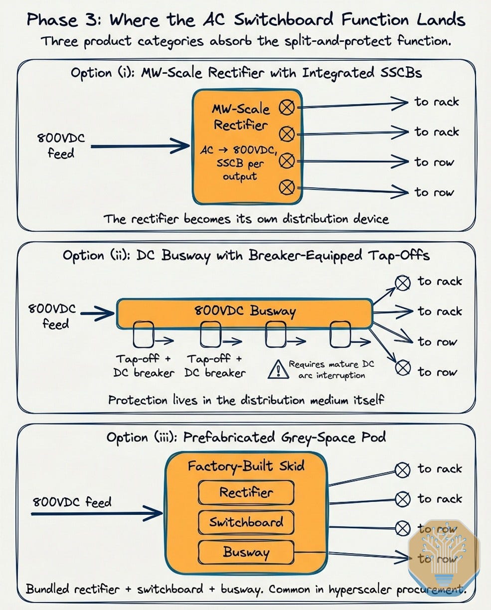
In Phase 3, the AC switchboard’s function of splitting one feed into multiple protected outputs has to land somewhere. Three product categories are positioned to absorb it: (i) MW-scale rectifiers built with multiple outputs and integrated SSCB protection per output, turning the rectifier into its own distribution device; (ii) DC busway with breaker-equipped tap-off boxes that hold protection in the distribution medium, once DC-rated tap-offs with adequate arc interruption mature; and (iii) prefabricated grey-space pods that bundle rectifier, switchboard, and busway into a factory-built skid, particularly for hyperscaler procurement.
Source: SemiAnalysis
Major AC switchboard incumbents (Schneider Electric, ABB, Eaton, Vertiv) have not named discrete 800VDC switchboard products. ABB’s October 2025 Nvidia partnership covers distribution inside its “modular power block” rather than as a standalone switchboard. EPEC Solutions sells a publicly marketed 800VDC LV switchboard with high-interrupting-capacity DC breakers. We expect the discrete switchboard to retain a niche in retrofits with existing single-output rectifiers, and where operators want vendor-neutrality across the rectifier and protection layers.
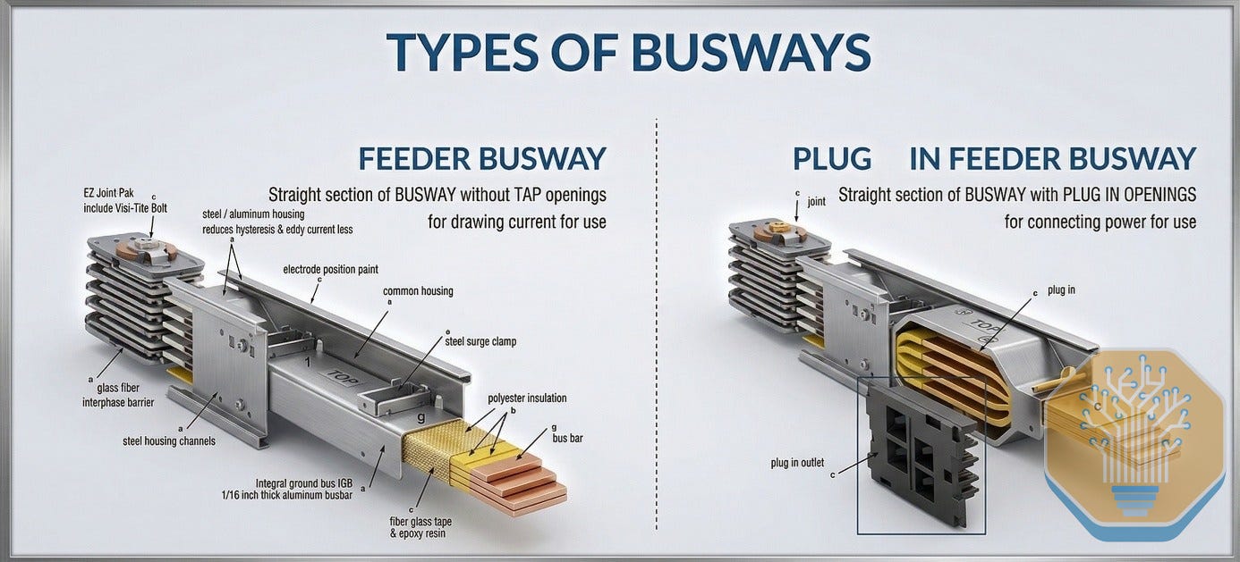
Once the power is rectified, a DC busway replaces AC busway for hall-level 800VDC distribution. In traditional AC datacenters, busway systems have modular plug-in connections called tap-offs that branch power to individual racks or rows, similar to outlets on a power strip. You can add or remove these while the busway is energized. A feeder-only busway, by contrast, has no intermediate openings or tap-offs. Power enters at one end and exits at the other end or at predefined termination points.
Source: SemiAnalysis
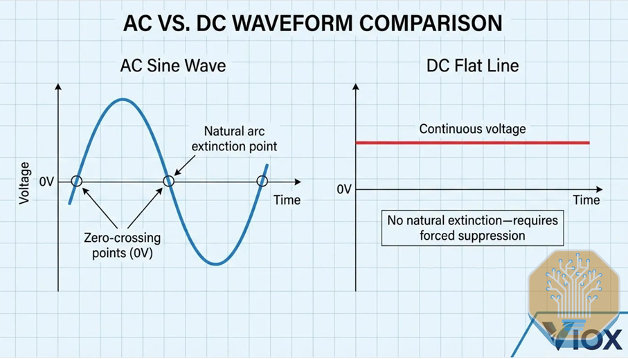
We expect early 800VDC deployments to use feeder-only busway because, essentially, tap-offs become more complex. At 800VDC, interrupting current under load creates a sustained arc (a plasma discharge producing extreme heat) that does not self-extinguish because DC has no zero-crossing point, while AC arcs naturally extinguish 100-120 times per second as the waveform crosses zero. Besides, DC-rated tap-off units with adequate arc interruption are physically larger, making them impractical today. Delta and ABB have publicly disclosed 800VDC busway programs, and we expect other major busway vendors like Legrand and EAE to follow in 2026.
To address these challenges, multiple proven protection paradigms exist at this voltage class from adjacent industries. The likely implementation combines multiple approaches, one being new generations of circuit breakers. More specifically, following the same solid-state trend already underway with Solid State Transformers, Solid State Circuit Breakers (SSCBs) are now being adopted. SSCBs use SiC or GaN to interrupt fault current in microseconds. Because semiconductor switches can simply stop conducting with no physical contact separation, there is no arc to extinguish in the first place.
Source: VIOX
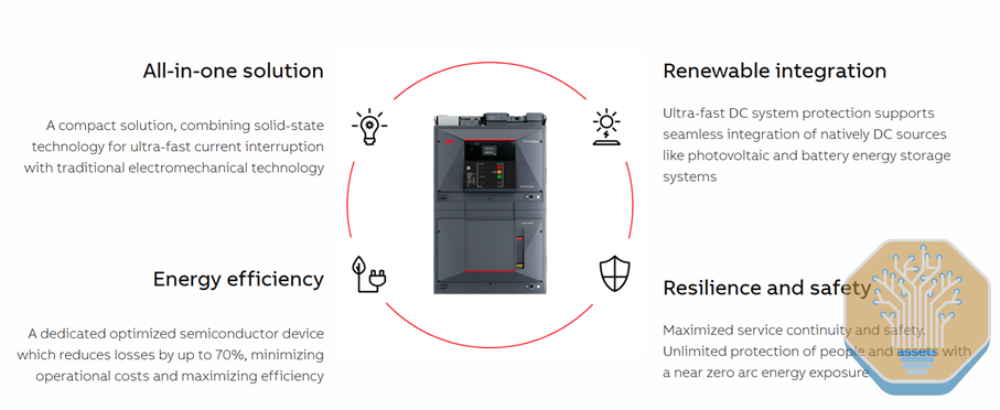
The new-generation circuit breakers are already commercialized today. ABB has the Emax 2 (1500V DC) used in solar, energy storage or marine, as well as the SACE Infinitus (solid-state, 1000V/2500A, datacenter adaptation with Nvidia announced October 2025). LS Electric has the first UL-certified DC molded case circuit breaker at 1500V, listed for datacenter applications.
Source: ABB
Alternative Path Using LV Solid State Transformers
An emerging alternative to the centralized AC/DC rectifier is using LV SSTs. It performs the same conversion, 415V AC to 800VDC in the grey space or outdoors, but in a more compact and programmable form factor. The LV-SST sidesteps the 3,300V-class SiC supply constraint that gates MV-input SSTs, making it the earlier-to-market SST variant.
What Happens in the White Space: From the Power Rack to the Battery Rack
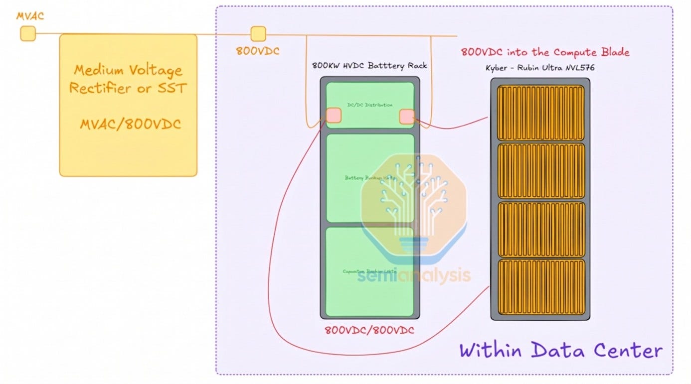
As you can imagine, in Phase 3 we no longer need the Power Rack doing the 800VDC conversion. Instead, we salute a new friend, the battery rack.
The battery rack shares most of the power rack’s components and functions. The main difference is that it no longer performs AC-DC rectification, because it receives 800VDC directly from the grey space. Three main components remain:
DC/DC distribution units: manage power distribution, switching, and monitoring across the 800VDC bus. They do not step-down voltage. The full 800VDC travels from the battery rack to the compute blade.
BBU shelves: provide ride-through power during supply interruptions.
Supercapacitors (optional): absorb microsecond-to-millisecond transients that batteries are too slow to catch. They sit between the DC bus and the BBU, handling fast voltage excursions.
Source: SemiAnalysis
The battery rack sits generally at the same row level as the power rack it replaces, although some operators are deploying these in the adjacent grey space or in outdoor enclosures. The trade-off is simple: rectifiers go away, BBU and supercapacitor content goes up. We expect content per MW for the battery rack to reach around $200k/MW.
We covered supercapacitor chemistry and technical specifications in our deep dive on AI training load fluctuations. Part 2 of this 800VDC series will go deeper on supercapacitor economics, cell chemistry, the vendor landscape, and the practical tradeoffs of deploying them in production.
BBU modules scale up
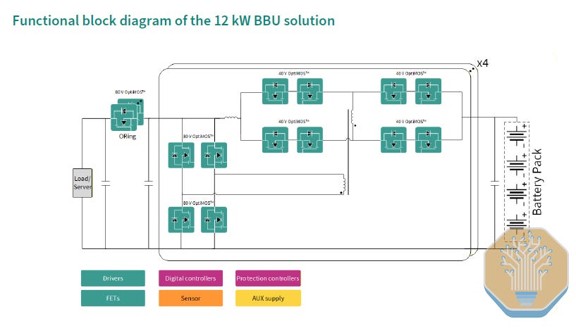
Current modules are rated at roughly 5.5kW. With Rubin Ultra and 800VDC architectures, individual module wattage rises to 8-12kW. Infineon’s BBU roadmap, announced in March 2025, uses modular 4kW Partial Power Converter cards that parallel to 12kW per unit at up to 99.5% peak efficiency.
Delta, at GTC 2026, went further at the shelf level: its new 110kW power shelves embed 80kW of BBU capacity each, totaling 480kW across a six-shelf rack. Higher rack power demands proportionally more backup energy per rack, and higher-wattage modules deliver that energy with fewer physical modules, preserving space in the power rack.
Source: Infineon
What Happens at the Facility Level
After analyzing the complete transformation of the grey space and the white space, the facility level is the part that changes least.
Here, cooling stays on AC. Chillers, pumps, and fans still run on AC motors, requiring DC-to-AC inverters. Delta unveiled a 2.4MW In-Row CDU supporting 800VDC at GTC 2026, the first major cooling component engineered for native DC. But the full stack (chillers, compressors, pumps, building controls) remains AC-dependent, and no vendor sells an integrated DC-native cooling system.
Generator architecture is already loosening at some hyperscalers independently of 800VDC. Meta is likely bypassing generators at new sites entirely, and Microsoft’s new designs use partial generator coverage. 800VDC could accelerate that direction, as supercapacitors, BBUs, and BESS form a distributed backup hierarchy that absorbs the functions generators used to own.
Medium Voltage Rectifiers: Is There Room for Everyone?
One reasonable question to ask is why power is rectified at the LV level and not directly from MV? The answer comes from semiconductor ratings. Rectifying from 13.8kV or 34.5kV requires devices rated above 10kV, which barely exist in commercial form today. That said, the gap is closing, and Wolfspeed’s 10kV SiC MOSFET has been commercially available as bare die since March 2026.
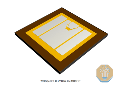
Source: Wolfspeed
The development of SiC MOSFETs above 10kV opens the door to a second evolution of Phase 3, where even the LV equipment drops out of the main power bus. Continuing the trend, this collapses additional conversion steps and brings new efficiency gains.
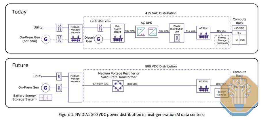
Source: Wolfspeed
The end state of our HVDC timeline will push even further. Even though conventional rectifiers with series-stacked silicon devices can handle MV rectification, an emerging technology promises to do it in a much more efficient, compact, and faster way. That technology is our protagonist for the next chapter of our journey: Solid State Transformers.
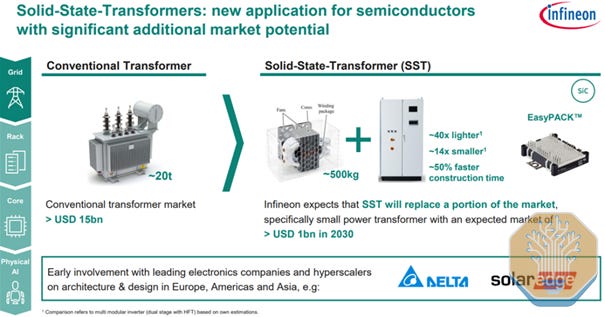
Source: Infineon
Phase 4 (>2029): SSTs, the End-State
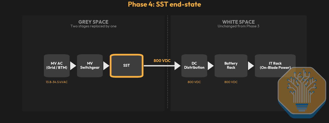
Source: SemiAnalysis Industrials Model
Finally, we get to the holy grail of DC power distribution: Solid State Transformers, or SSTs. These are a new category of power electronic devices that replace conventional iron-core transformers with high-frequency, semiconductor-based converters.
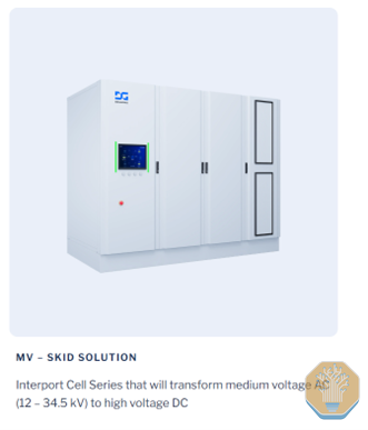
Source: DGMatrix
Phase 4 and its datacenter layout is very similar to Phase 3. The major change is that the SST replaces the LV AC-DC rectifier and low-voltage transformer with a single piece of equipment that converts directly from medium voltage to 800VDC. If we consider the ending of the previous section, the possibility of using a MV rectifies that rectifies directly from MV AC, the architecture is essentially identical.
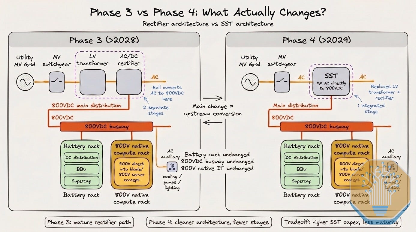
Source: SemiAnalaysis
In a Nutshell: Solid-State Transformers
Introduction to SSTs
An SST does the same job as the massive iron-and-copper transformers in every datacenter’s grey space: step voltage from utility-level medium voltage to a level IT equipment can use. A conventional transformer uses magnetic induction at grid frequency. An SST uses semiconductor switching stages to achieve the same conversion in a fraction of the volume.
The datacenter SST is a three-stage device. The input stage converts AC to DC, handling the dangerous medium-voltage level (13.8 to 45kV) using SiC MOSFETs rated at 3,300V or higher. The isolation stage is where the size reduction happens. A high-frequency transformer steps the voltage down while providing galvanic isolation between the utility / power-source and the datacenter. The output stage produces the final 800VDC that the distribution system needs, with no inverter required.
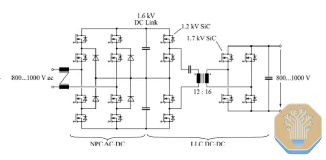
Source: ETH Zurich
Pros and Cons of SSTs
SSTs’ core value proposition is energy efficiency, which translates directly to OPEX savings or unlocked compute capacity. By collapsing the medium-voltage transformer and rectifier into a single power-electronic stage, SSTs eliminate two conversion steps from the electrical chain. Vendors target up to 15% total system efficiency improvement, claiming the path rises from around 82-85% towards over 97%.
SSTs are also dramatically smaller. A conventional transformer operates at 50 or 60 Hz and needs a massive iron core. An SST switches at 20,000 Hz or higher, shrinking the core by roughly 90%. That is where Infineon’s claimed 40x weight reduction and 14x size reduction (!) come from.
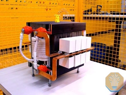
Source: EENews
In addition, SSTs are programmable. A conventional transformer steps voltage at a fixed ratio. An SST actively regulates output, adjusting under load. It also supports bidirectional power flow (pushing power to the grid during demand response, or charging a BESS). That said, SSTs with bidirectional capability and integrated BESS may trigger DER reclassification by the interconnecting utility, requiring IEEE 1547/2800 compliance.
One additional major value proposition from SSTs is input flexibility. Some SST architectures extend this flexibility into multi-port topology, where a single device aggregates several inputs (utility AC, on-site generation, DC sources) and routes power across multiple outputs in software, including bidirectionally. The case for multi-port is that it reduces stranded power between zones and lets operators orchestrate flows across the site.
Reliability
Conventional transformers last 30-40 years as passive devices. No SST vendor has published field reliability data at datacenter scale, as the longest deployment is the Hitachi-ABB PETT on Swiss Federal Railways, running since 2011. SSTs concentrate heat in semiconductor junctions and require active cooling, with DG Matrix using integrated liquid cooling and Novos Power using air cooling through proprietary insulation.
ETH Zurich’s comparative evaluation found that a line-frequency transformer paired with a SiC rectifier can match SST efficiency and functionality. Datacenter-scale SSTs depend on SiC MOSFETs at 3,300V+ for the MV input stage, still in limited production. GaN, capped at roughly 650V, serves only downstream stages converting 800VDC to rack-level voltages.
Current Efficiency State
The best public SST benchmark comes from ETH Zurich: 98% efficiency at 400kW in a 13.2kVAC-to-800VDC prototype presented at INTELEC 2025. Johann Kolar frames 98.0-98.5% as today’s state of the art for full-scale SSTs, with 99% as the next engineering target for datacenter units.
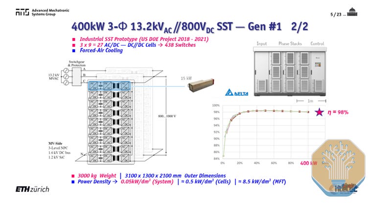
Source: ETH Zurich
Different vendors now converge on that 98.5% ceiling: DG Matrix’s Interport platform claims up to 98.5%, Amperesand’s third-generation system claims greater than 98.5%, and Heron Power’s Heron Link targets 98.5% MV-to-rack efficiency. Novos Power reports peak efficiencies over 98%. These are encouraging, but datacenters will need 3-6MW units sustaining 99%+ efficiency under continuous load.
Two data points suggest the scale-up is underway. Chinese trade press reports that China XD Electric has deployed 2.4MW datacenter SSTs under the “East Data West Compute” program. NC State’s FREEDM Systems Center, the academic foundation which marked the origin of DG Matrix, has demonstrated 210 kHz switching at 3.3kV SiC with a 99% efficiency target for modular DC-DC SST variants.
Vendor Landscape
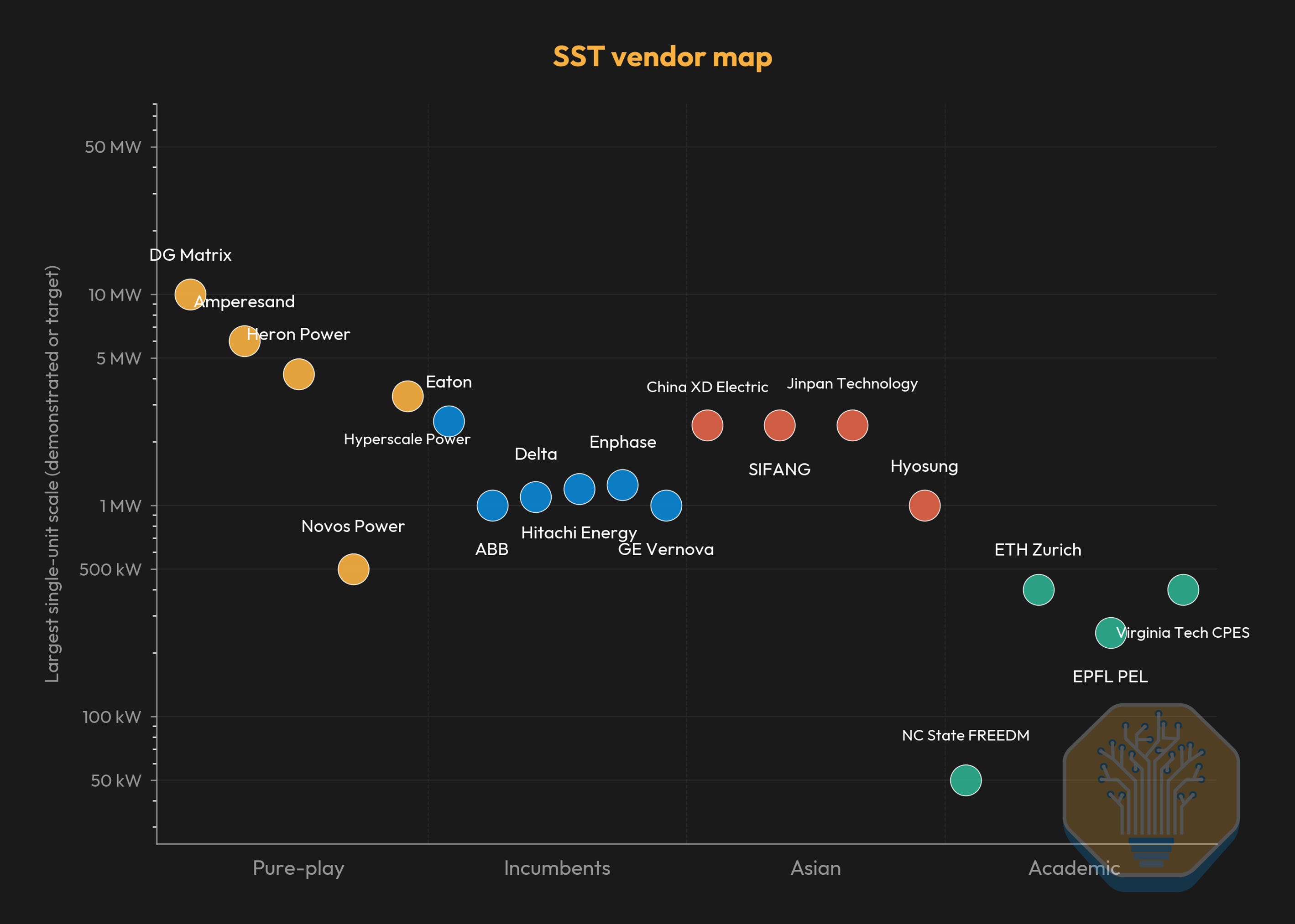
Source: SemiAnalysis Industrials Model
The vendor landscape is moving fast. DG Matrix (ABB-backed, Infineon SiC supply deal) is shipping pre-certification units and targeting UL certification by end of Q2 2026. It is the only SST included in Nvidia’s MGX reference architecture. Amperesand targets 30MW of commercial deployments in 2026. Heron Power is building a 40GW US manufacturing facility for its 4.2MW Heron Link units.
Within the SST category, products are bifurcating along LV and MV input. DG Matrix and Amperesand are pursuing both, starting with LV-input SST skids (3.2-4.8 MW) that can be deployed today alongside existing AC distribution, and following with MV-input units as 3,300V-class SiC matures. Heron Power and Novos Power are concentrating on direct MV-input units that collapse the LV transformer and rectifier into a single device. Both paths converge on 800VDC at the output, but the LV path offers a shorter time-to-deployment at the cost of retaining the upstream MV-to-LV transformer.
Source: DG Matrix
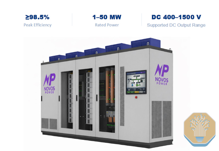
Novos Power claims a direct MV-to-800VDC SST with 50% smaller footprint and air cooling. On the incumbent side, Eaton acquired Resilient Power Systems in August 2025 for SST expertise. More than $320M flowed into SST startups in the twelve months ending March 2026.
Source: Novos Power
Datacenter Layout Implications
The SST eliminates the LV equipment at ∼$0.55M/MW and the Phase 2 rectifier at ∼$0.20M/MW. At an estimated SST cost of ∼$1.0-1.5M/MW, we expect the first instances of SSTs to come at an upfront Capex premium over directly replaced equipment.
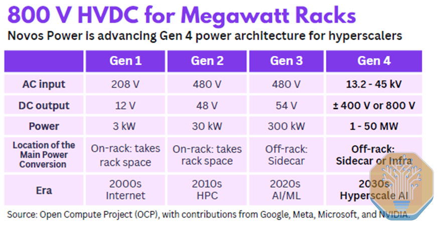
Source: Novos Power
The rest of the electrical architecture remains the same as in Phase 3. The 480V AC auxiliary bus for cooling, lighting, and facility systems carries over unchanged. On the IT rack-side, we expect that by the time SSTs are deployed, compute trays are already 800VDC native. However, we could see deployments of SST adoption with 800V microgrid and IT racks using a DC-DC power shelve converter, which could accelerate the adoption.
On Phase 4 timings, this emerging technology is still in design phase, and we don’t expect major SST adoption at scale until early 2029. That said, we are aware that all major hyperscalers are running pilot and testing with main SST vendors, with commercial contracts already in place. As we cover in the following section, technology development itself will not be the only factor determining the adoption curve here. Regulatory framework and standards is a big one. In the SST space, no vendor has completed UL certification for datacenter SST deployment as of May 2026.
The SST Market Opportunity and TAM sizing
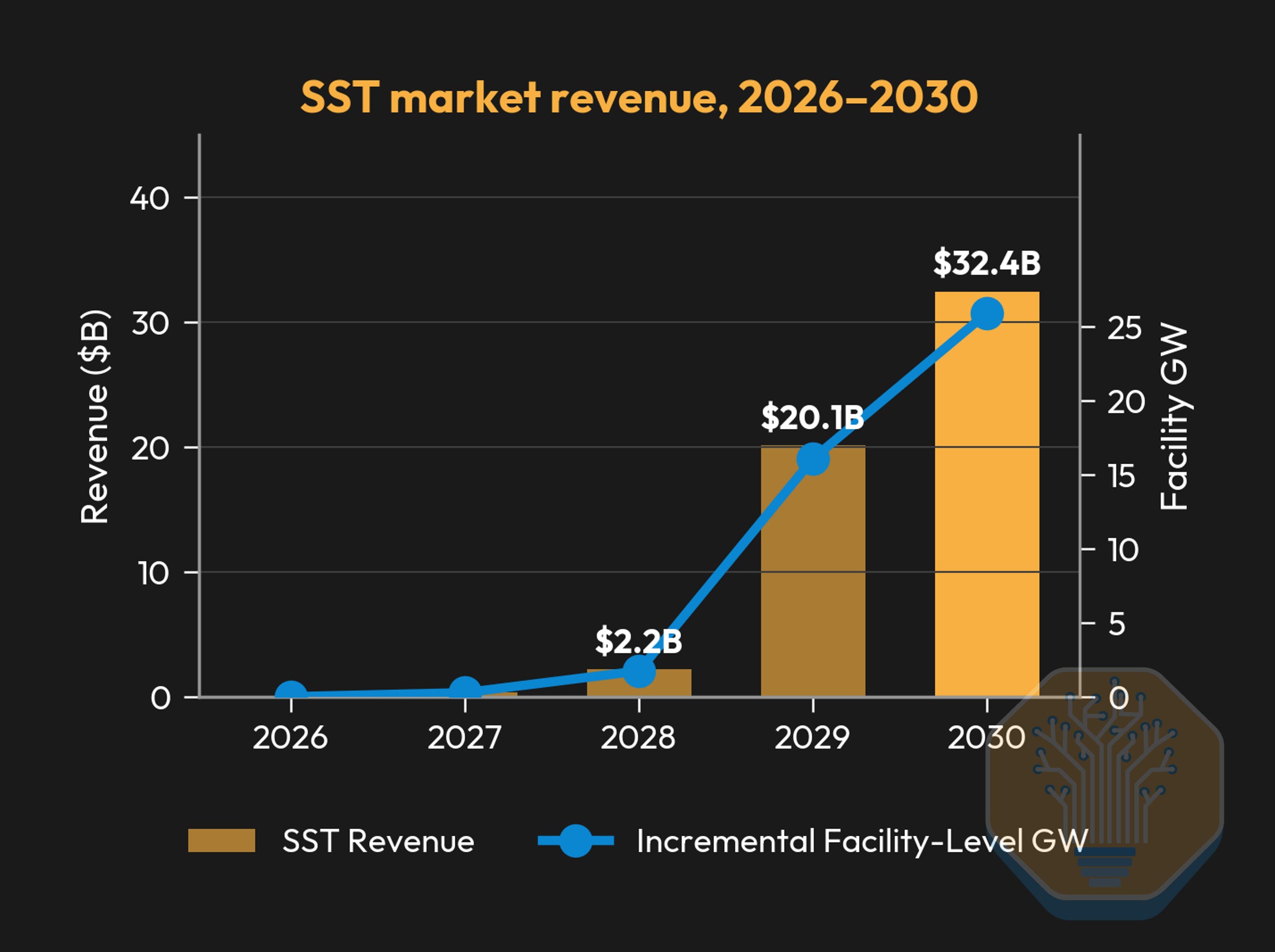
By 2030, we expect SST TAM to reach ~$32B, capturing the demand displaced from the sidecar layer plus the incremental MV-to-800VDC conversion. We consider a content of $1.25M/MW. A portion of this opportunity is contested by MV rectifiers, but we expect SSTs to capture the majority share.
Source: SemiAnalysis Industrials Model
Datacenter Layout Summary: Total Cost Barely Moves, Content Shifts, Efficiency Climbs
Electrical System Cost
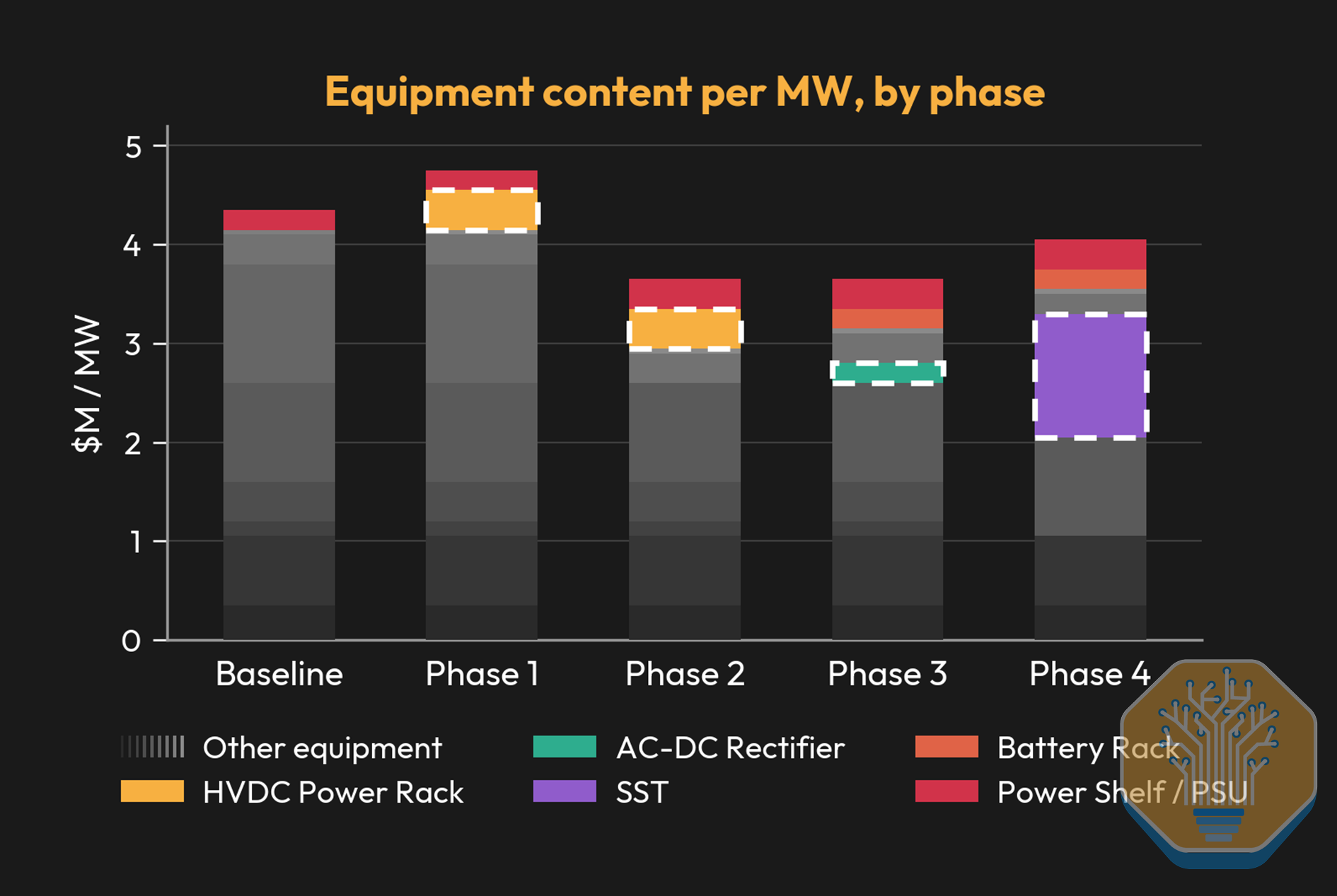
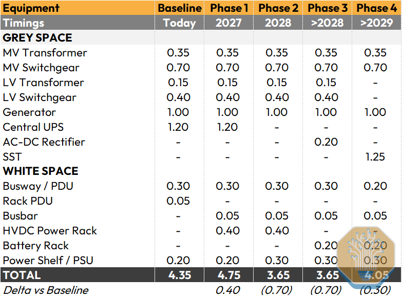
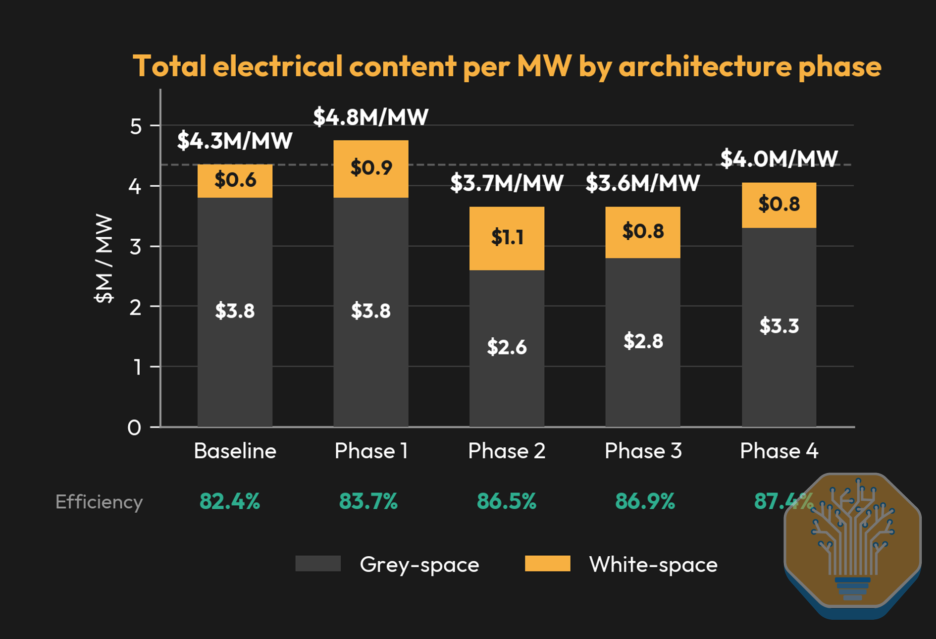
Total electrical content per MW stays in a $3.6-4.8M band across four of the five architectures we model. The main headline is a content migration from grey space to white space, and the resulting change in equipment mix.
Source: SemiAnalysis Industrials Model
Grey space content shrinks in Phase 2 as the centralized UPS ($1.2M) exits. White space peaks in Phase 1 because the HVDC power rack arrives. By Phase 4, total content climbs to $4.0M as the SST replaces the LV transformer and rectifier.
Electrical System Efficiency
We calculate the baseline AC power path at 82.0% cumulative efficiency across seven conversion stages. The VRM (92%) and PSU (94%) are the two largest single-stage losses. The VRM stays in every architecture, but the PSU’s loss is the largest penalty the 800VDC transition can eliminate. Phase 1 barely improves to an estimated 83.7%. The UPS double-conversion loop still eats 3 percentage points, and the new power rack rectifier (97.5%) plus DC-DC stage (97.0%) only marginally outperform the old single-stage PSU.
The real jump comes in Phase 2 (86.5%) when UPS elimination cuts the chain from seven stages to five. Phase 3 pushes to 86.9% because the centralized grey-space rectifier operates at MW scale (higher efficiency than modular rack-mounted units) and 800VDC hall-level distribution eliminates AC skin effect and reactive power losses. We estimate Phase 4 to reach 87.4% as the SST replaces two stages with a single device.
At 1GW of IT load, the Phase 2 gain translates to roughly 58MW of continuous grid power savings. Phase 3 extends that to 63MW and Phase 4 to 69MW. Nvidia cites up to 5% efficiency improvement, implying roughly 50MW at 1GW. Our Phase 4 efficiency delta calculations of 5% vs baseline matches Nvidia’s reported figures.
The Other Side of the 800VDC Transition: Challenges and Limitations
So far, we’ve mapped out a promising path, but as always, various challenges will arise along the way. We now unpack four main obstacles that will determine how fast 800VDC moves from small-case pilots to broader adoption.
Challenge 1: Regulation, Safety and Grounding
Regulation
The National Electrical Code (NEC), published by NFPA on a three-year cycle, governs electrical installation in the United States. Adopted by nearly every state and municipality as binding law, it determines whether an operator can build to a standard design or must negotiate site-by-site with the local Authority Having Jurisdiction (AHJ). Full 800VDC code support targets NEC 2029. Pre-2029 deployments therefore require custom AHJ approvals and OEM-level UL certification for each site. This is workable for hyperscalers with in-house code engineering teams but could represent a meaningful barrier for colocation operators and smaller builders.
We see a useful parallel in the early days of the EV industry, where Tesla designed and approved its own internal safety frameworks because industry-wide standards had not yet arrived. Hyperscalers deploying 800VDC pre-2029 will be in a similar position.
NEC 2029 would already be fast by historical standards, considering prior DC power standardization timelines in marine, telecom, and EV. However, timelines could benefit from extreme buyer concentration with five hyperscalers and Nvidia as both demand creator and solution architect and an EV 800V component supply chain.
We think NEC 2029 will achieve partial provision, while full code maturity probably lands at NEC 2032 or 2035. Partial means the basic framework exists (voltage classification, conductor sizing, overcurrent protection) but DC-specific arc flash PPE tables, busway standards, and stored energy maintenance protocols will likely be absent.
Safety
The biggest safety risk is arc flash. IEEE 1584 does not cover DC, and NFPA 70E has no PPE table for 600-1000VDC. UL Solutions has launched a Direct Current Safety Research Consortium to build the missing hazard models, explicitly citing 800V DC datacenter architectures among the target applications.
Even beyond the code gap, daily reality may be harder. At 48V, a technician can hot-swap a server tray with minimal PPE. At 800V, many rack-adjacent tasks that were routine at 48V likely require a qualified person under NFPA 70E, with arc-rated clothing, insulated gloves rated to 1000V, and a face shield. Capacitor banks and BBU modules retain dangerous charge after power-down, and standard lockout-tagout procedures for AC do not account for stored DC energy. Multiple sources must each be verified de-energized before maintenance.
Flex, a major Nvidia manufacturing partner, has publicly advocated for in-depth hazard identification and safety training at 800VDC facilities.

Source: Flex
Grounding
Grounding cascades into protection-device count, fault behavior, insulation monitoring, personnel safety, and vendor compatibility, which makes it on the most consequential early design choice in an 800VDC facility.
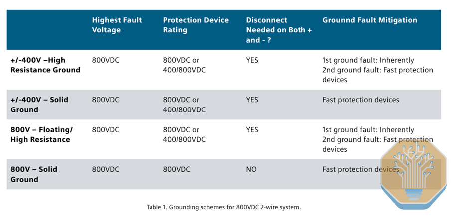
The Siemens/Nvidia paper “Protections for Data Centers Powered by Direct Current” identifies four options. A ±400V system can use high-resistance grounding (HRG), which tolerates the first ground fault and only requires fast interruption on the second, or solid grounding, which demands immediate clearing of any fault. An 800V monopolar system can float, with insulation monitoring on every branch, or run a solid-grounded return conductor.
Source: Siemens, Nvidia
The tradeoff is cost. HRG and floating systems need protection devices rated for the full 800VDC on both conductors plus insulation monitoring infrastructure. Solid-grounded-return cuts the protection device count but eliminates galvanic isolation between parallel converters. OCP Diablo 400 permits both ±400V bipolar and 800V monopolar, leaving the call to the operator.
The reality is that no industry consensus exists. SST and power-electronics vendors are optimizing around different grounding assumptions, which makes the choice a vendor-ecosystem commitment, not just a technical one.
Challenge 2: Cooling and Auxiliary AC Workloads
Cooling is the largest AC load in an 800VDC datacenter, and no vendor sells a DC-native cooling ecosystem. Some vendors like Delta and Danfoss are doing progress. Danfoss’s Turbocor compressors, dominant in datacenter chillers, run internally on DC at 700-813V. Danfoss also manufactures the VACON NXP variable-frequency drive, which accepts 640-1200 VDC input directly, placing 800V within its operating range. DCAirco ships 800V DC chillers for e-mobility at 4-8kW, 100-1000x too small for datacenter scale, but proof the refrigeration cycle works at this voltage.
Beyond cooling, switchgear operating mechanism, lighting, fire suppression pumps, building management sensors and security systems all run on AC. As Nvidia team presented at OCP Global Summit 2025, 800VDC reference architecture will retain an AC auxiliary bus alongside the 800VDC compute distribution for exactly this reason.
That said, the supply chain is moving. The Delta CDU noted above is the leading edge, but most auxiliary categories (lighting, fire suppression, security) lack DC variants. With datacenter industrial capex heading toward >$400 billion in 2026 and electrical equipment at 30-35%, the incentive to develop DC-native products is growing.

Source: Delta
Challenge 3: Supply Chain Standards
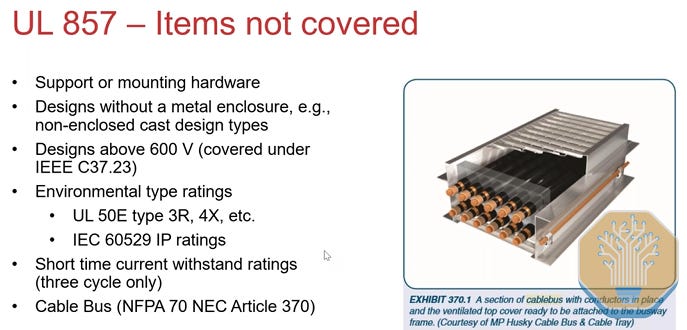
Innovation in DC distribution is ahead of codification, and standards still lag across most 800VDC equipment categories. Busway is a good example of progress. UL 857, the standard governing busway systems, originally capped coverage at 600V and defined values in root-mean-square (RMS). Edition 14, published in 2025, raised the ceiling to 1000VDC, and Edition 15 in development targets 1500VDC. Outside busway, certification paths remain absent, and every installation becomes a custom engineering project where the operator must qualify the product, negotiate conductor ratings, and obtain AHJ approval on a case-by-case basis.
Source: UL Solutions
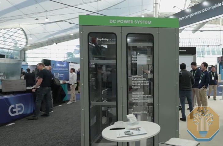
An OCP white paper targeting 2026 may help, and OCP working groups are coordinating with regulators and certification bodies to land initial standards by year-end 2026, but vendors are already presenting their prototypes. Delta demonstrated 800VDC air-cooled busway at OCP 2025, LS Electric exhibited DC power equipment at DistribuTECH 2026, and in almost all recent conferences the team has been present in, 800VDC-ready prototypes have been without a doubt the protagonists.
Source: LS Electric
Challenge 4: Grid Interconnection and Regulatory Pressure
As we covered in our deep dive on AI training load fluctuations at gigawatt scale, datacenter load-loss events during grid disturbances have become a serious concern for grid operators. 800VDC sharpens the problem by moving grid-facing behavior into software-defined power electronics (SST control algorithms, converter current limits, DC bus capacitance…).
Grid operators now have to model and constrain those dynamics, and the regulatory bar is also rising. NERC issued a Level 3 Essential Actions Alert (its highest tier) on May 2026 covering large computational loads, with a mandatory response deadline of August 3, and has proposed a Computational Load Entity registration for datacenters consuming 1MW+ within a 20MW+ aggregate at 60kV+. ERCOT’s NOGRR282 adds voltage and frequency ride-through requirements and mandates both PSS/E and PSCAD electromagnetic transient models for all large loads.
Why 800VDC raises the burden of proof
Traditional AC datacenters have a grid-facing vocabulary that planners can model: UPS transfer thresholds, ATS timing, motor-load behavior, generator controls, and composite load models like CMPLDW. None of that captures an 800VDC facility, where the response to a grid voltage dip depends on the SST control algorithm (grid-following vs grid-forming), BESS state of charge, instantaneous GPU load profile, and interactions between multiple parallel SSTs.
800VDC also collapses layers of the power stack. In an AC facility, the utility studies the interconnection and aggregate load while the operator engineers UPS, switchgear, and rack distribution independently. In an SST-based 800VDC facility, the same converter controls determine DC bus stability, fault ride-through, current limiting, harmonic injection, and post-fault load recovery. Interconnection therefore becomes an engineering product that requires EPC capabilities bridging power electronics design, grid-level dynamic modeling, and regulatory engagement. This is leading to new entrants like Aran Industries, building AI-native EPCs to deliver PE-stampable 800VDC engineering packages.
Understanding The No-So-Basics: The Physics Behind 800VDC
Why Going Super Dense Makes Low-Voltage Distribution Break: Heat and Weight
At a fixed power level, raising voltage from 54V to 800V cuts current by ~15× and resistive losses by ~220×. That is what makes 800VDC a step-change in copper mass, thermal load, and distribution cost.
Start with the power equation:
For a fixed rack power P, raising V reduces I linearly. Lower current means smaller conductors, less copper mass, and easier routing.
Ohm’s Law gives the voltage drop across a conductor of resistance R:
That drop is the energy dissipated as heat in the conductor. Substituting into the power equation yields the resistive loss equation:
Current appears squared, so the voltage-to-loss relationship is quadratic, not linear. This is the equation that makes 800VDC inevitable.
A working example at 600kW rack power (Kyber-class, Vera Rubin Ultra NVL576):
At ~54 VDC (today’s standard):
At 800 VDC:
That’s a 14.8× reduction in current. Now apply the loss equation. For the same conductor resistance R, the I² ratio implies:
Resistive heating at 54 V is roughly 219 times higher than at 800 V for the same conductor. In the more commonly cited comparison using 48 V:
In practice, operators do not keep the same conductor and pocket all 219-278× of loss reduction. They shrink the copper, trading loss headroom for reductions in weight, cost, and routing space. Even after right-sizing for 800V, the efficiency gain remains transformative.
800VDC vs. ±400VDC: The Topology In Question
‘800 VDC’ may refer to two distinct electrical configurations, and the distinction matters for deployment strategy, safety engineering, and downstream semiconductor selection. ‘800 VDC’ may refer either to a single-ended 800V bus or a bipolar ±400V bus (800V pole-to-pole):
Single-ended 800V
In a single-ended 800VDC architecture, the bus is a single 800V rail referenced to return, plus protective earth. At 1MW, the bus carries 1,250A. Lower current means smaller conductors, smaller connectors, and lower I²R losses throughout the distribution path. The bus structure is also simpler to implement because it does not rely on maintaining symmetry between two rails. Power stages can be designed directly around the full bus voltage using standard high-voltage devices and conventional converter topologies. No midpoint to sense, regulate, or control.
Bipolar ±400V
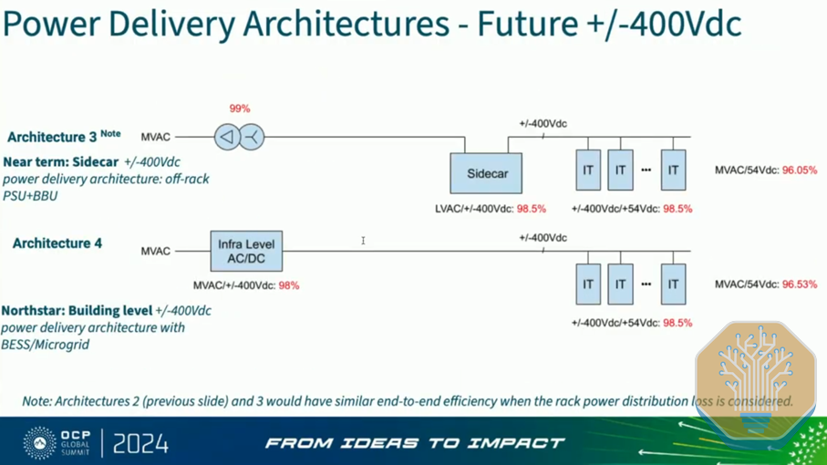
The alternative splits that 800V into two symmetric 400V rails around a grounded midpoint: three power conductors (+400V, midpoint, -400V) plus protective earth. The load still sees 800V across its input, but each rail sits only 400V from ground. The central argument here is not electrical, but economic. 400V power electronics are mature because the EV industry built at scale on 400V platforms. Google stated at OCP EMEA 2025 that selecting 400VDC “allows us to leverage the supply chain established by electric vehicles”. The OCP Diablo 400 specification considers a disaggregated power rack converting 3-phase AC to ±400VDC at 100kW to 1MW per rack. The spec also includes 800VDC monopolar as a design option, leaving the door open.
There’s also a tradeoff. That third conductor must be routed, terminated, and protected at every point in the power path. Across thousands of racks, it adds meaningful copper, connector hardware, and installation labor, and it complicates hot-swap connector design where the midpoint must make and break contact in a controlled sequence to avoid transient voltage spikes.
Source: OCP
Behind paywall we will now discuss the main winners and losers of the 800VDC revolution, and who is better positioned to be benefited from the transition.